

Multi-degree-of-freedom antenna test platform
A test platform and a technology of degrees of freedom, applied in the direction of antenna radiation pattern, etc., can solve the problems of long measurement period, maneuvering transfer, space position adjustment, stable adjustment, test accuracy and efficiency defects, and large antenna test interference, etc., to achieve The effect of improving test performance, improving operation stability and practicality, and good maneuverability
- Summary
- Abstract
- Description
- Claims
- Application Information
AI Technical Summary
Problems solved by technology
Method used
Image

Examples
Embodiment 1
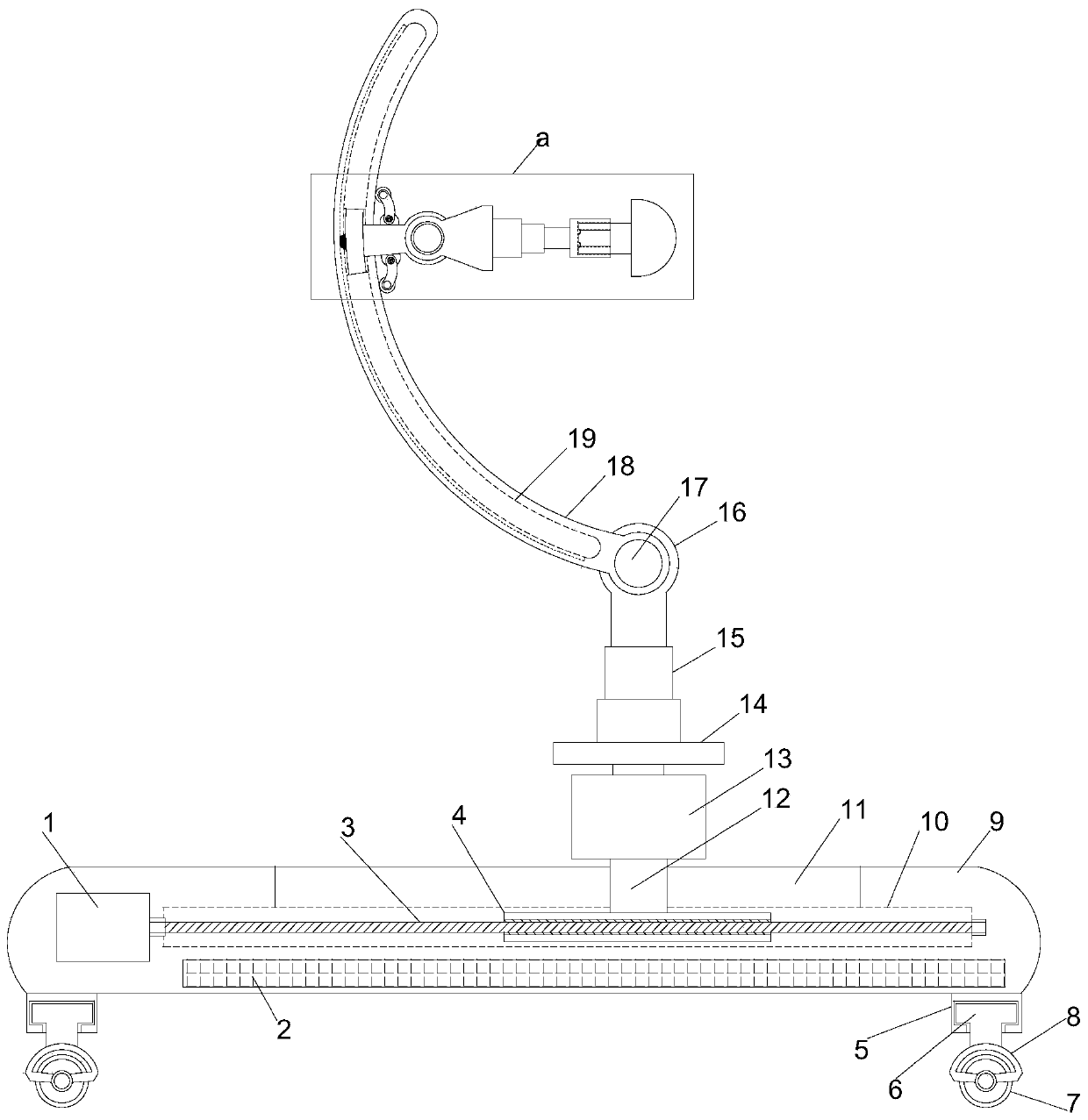
[0022] see Figure 1~3 , in an embodiment of the present invention, a multi-degree-of-freedom antenna test platform includes a horizontally arranged mobile mounting plate 9, and the four corners of the lower end of the mobile mounting plate 9 are vertically provided with steering bearing sleeves 5, and the steering bearing sleeves 5 are all vertically arranged. Steering shafts 6 are provided, and the steering shafts 6 all stretch out the steering bearing sleeve 5 downwards, and the lower ends of the steering shafts 6 are provided with steering wheel frames 8, and the lower ends of the steering wheel frames 8 are all provided with moving wheels 7 through the rotating shafts. The middle position of the mobile installation plate 9 is horizontally provided with a mobile guide groove 10, and the inside of the mobile installation plate 9 on the lower side of the mobile guide groove 10 is horizontally embedded with a battery pack 2, and the left end of the mobile guide groove 10 is ho...
Embodiment 2
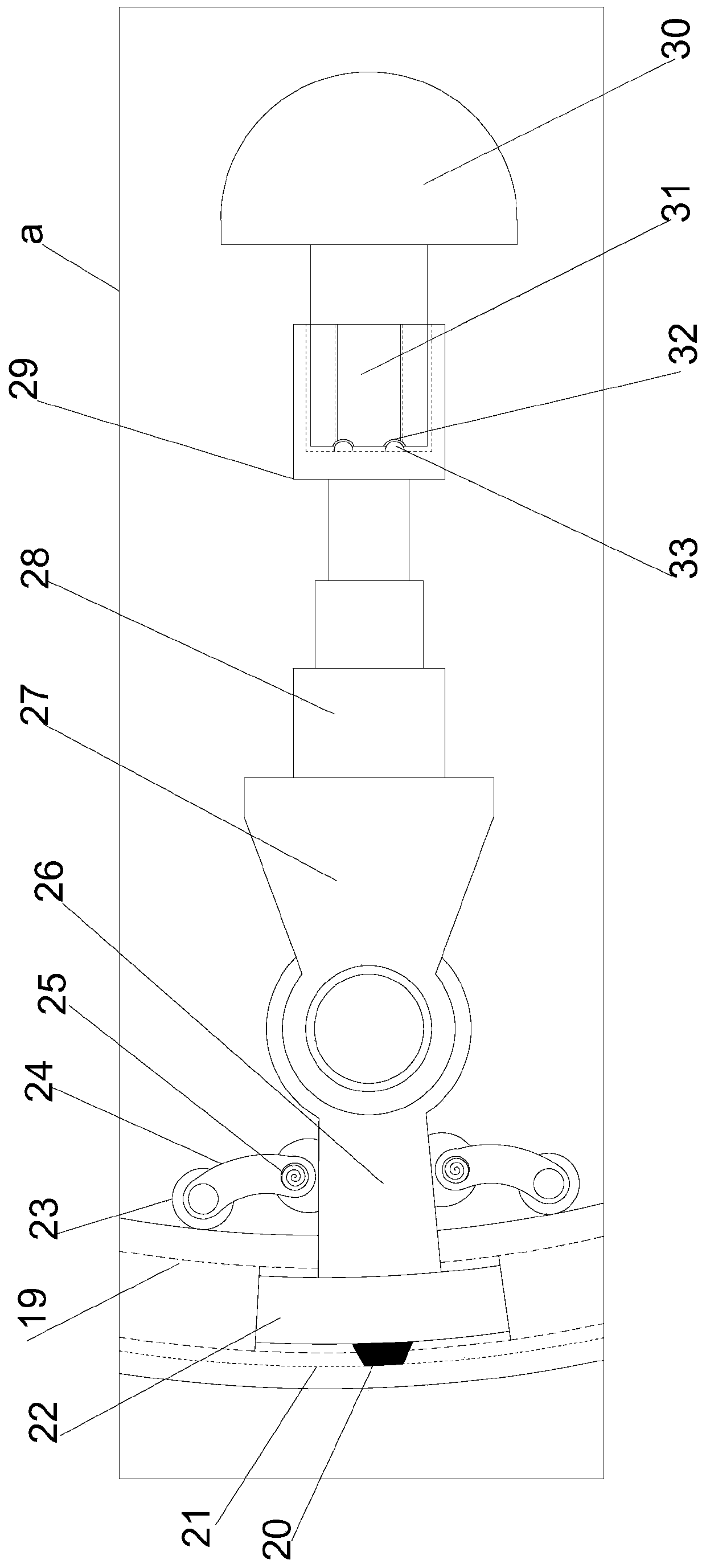
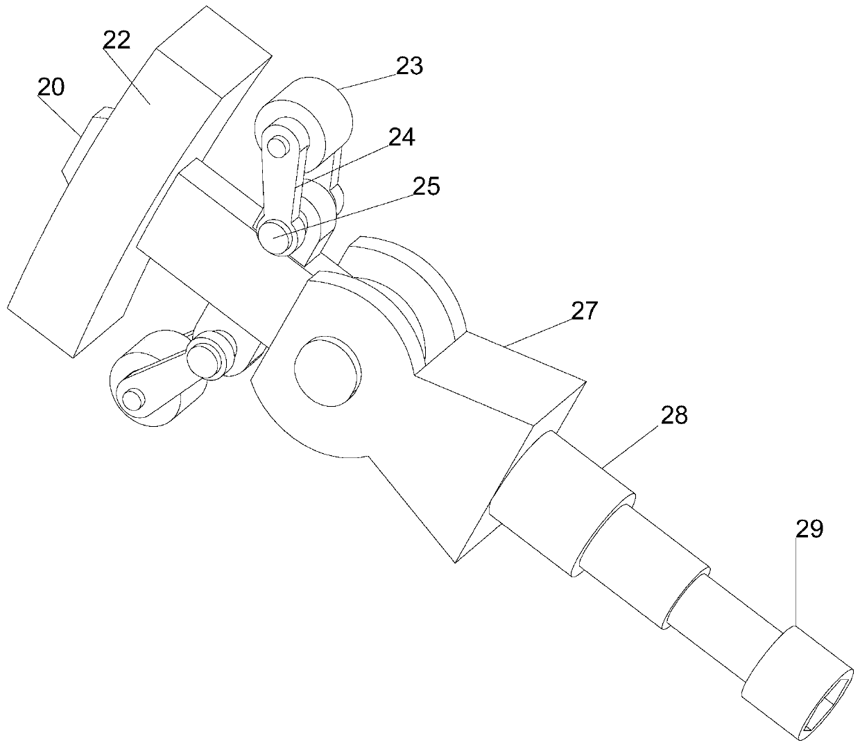
[0025] On the basis of Embodiment 1, through the cooperation of the steering bearing sleeve 5, the steering shaft 6, the steering wheel frame 8 and the moving wheel 7, the device has a good ability to turn and move, and the arc-shaped conductive slider 20 and the arc-shaped conductive The cooperation of the chute 21 realizes coupling power supply, which significantly improves the power supply stability of the device, and the storage battery can make the device run independently for a period of time, which improves the practicability of the device.
PUM
 Abstract
Description
Claims
Application Information