Optical system, camera module, electronic device and automobile

An optical system, relational technology, used in the field of photography

Inactive Publication Date: 2020-06-09
TIANJIN OFILM OPTO ELECTRONICS CO LTD
View PDF0 Cites 6 Cited by
  • Summary
  • Abstract
  • Description
  • Claims
  • Application Information

AI Technical Summary

Problems solved by technology

[0003] Based on this, it is necessary to provide an op...

Method used


Image

  • Optical system, camera module, electronic device and automobile
  • Optical system, camera module, electronic device and automobile
  • Optical system, camera module, electronic device and automobile

Examples


no. 1 example

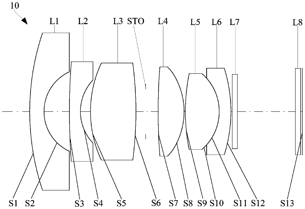
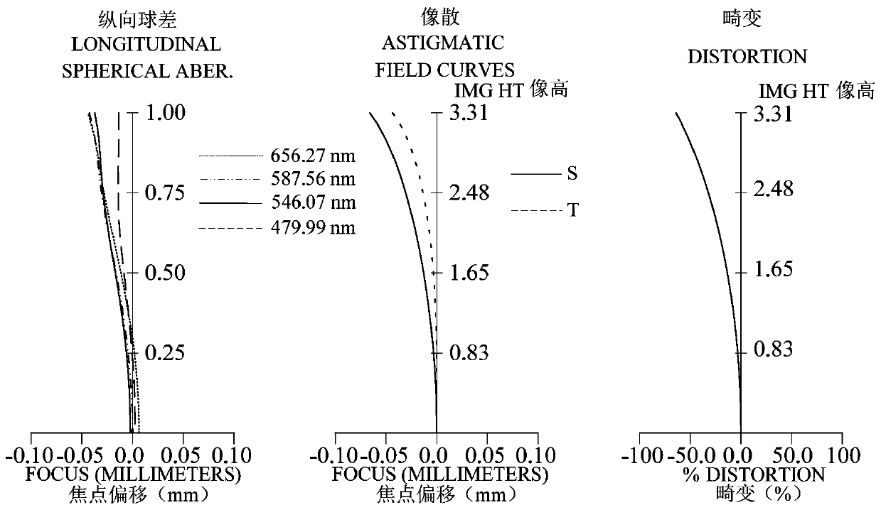
[0087] refer to figure 1 , in the first embodiment, the optical system 10 sequentially includes a first lens L1 with negative refractive power, a second lens L2 with negative refractive power, a third lens L3 with positive refractive power, and a light lens from the object side to the image side. The stop STO, the fourth lens L4 having a positive refractive power, the fifth lens L5 having a positive refractive power, and the sixth lens L6 having a negative refractive power. figure 2 A longitudinal spherical aberration diagram (mm), an astigmatism diagram (mm) and a distortion diagram (%) of the optical system 10 in the first embodiment are included. In addition, the reference wavelengths of the following embodiments (the first embodiment to the sixth embodiment) are all 587.56 nm.

[0088] The object side S1 of the first lens L1 is convex, and the image side S2 is concave.

[0089] The object side S3 of the second lens L2 is convex, and the image side S4 is concave.

[009...

no. 2 example

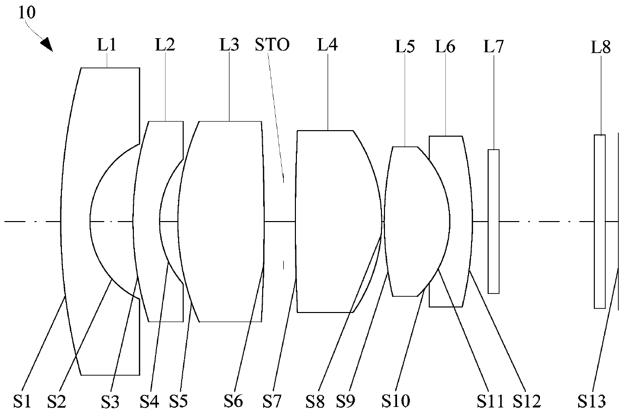
[0118] refer to image 3 , in the second embodiment, the optical system 10 sequentially includes a first lens L1 with negative refractive power, a second lens L2 with negative refractive power, a third lens L3 with positive refractive power, and a light lens from the object side to the image side. The stop STO, the fourth lens L4 having a positive refractive power, the fifth lens L5 having a positive refractive power, and the sixth lens L6 having a negative refractive power. Figure 4 A longitudinal spherical aberration diagram (mm), an astigmatism diagram (mm) and a distortion diagram (%) of the optical system 10 in the second embodiment are included. The ordinate of the astigmatism diagram and the distortion diagram is the image height corresponding to the maximum viewing angle of the optical system 10, and the unit is mm.

[0119] The object side S1 of the first lens L1 is convex, and the image side S2 is concave.

[0120] The object side S3 of the second lens L2 is conve...

no. 3 example

[0131] refer to Figure 5 , in the third embodiment, the optical system 10 sequentially includes a first lens L1 with negative refractive power, a second lens L2 with negative refractive power, a third lens L3 with positive refractive power, and an optical lens L3 from the object side to the image side. The stop STO, the fourth lens L4 having a positive refractive power, the fifth lens L5 having a positive refractive power, and the sixth lens L6 having a negative refractive power. Figure 6 A longitudinal spherical aberration diagram (mm), an astigmatism diagram (mm) and a distortion diagram (%) of the optical system 10 in the third embodiment are included. The ordinate of the astigmatism diagram and the distortion diagram is the image height corresponding to the maximum viewing angle of the optical system 10, and the unit is mm.

[0132] The object side S1 of the first lens L1 is convex, and the image side S2 is concave.

[0133] The object side S3 of the second lens L2 is ...


PUM

PropertyMeasurementUnit
Optical lengthaaaaaaaaaa

Abstract

The invention relates to an optical system, a camera module, an electronic device and an automobile. The optical system includes, in order from an object side to an image side: a first lens having negative refractive power and having a convex object-side surface and a concave image-side surface; a second lens having negative refractive power and having a convex object-side surface and a concave image-side surface; a third lens with positive refractive power; a fourth lens with positive refractive power; a fifth lens with positive refractive power; a sixth lens having negative refractive powerand having a concave object-side surface and a convex image-side surface; and a middle diaphragm. The optical system meets the relation that f456/f is larger than 0 and smaller than 3, wherein f456 isthe combined focal length of the fourth lens, the fifth lens and the sixth lens, and f is the effective focal length of the optical system. When the above relation is satisfied, the miniaturization design of the system can be realized, and the imaging definition of the system can be improved.

Description

technical field [0001] The invention relates to the field of photography, in particular to an optical system, a camera module, an electronic device and a car. Background technique [0002] With the development of camera equipment, especially for the vehicle industry, users have higher and higher technical requirements for vehicle cameras such as front view, automatic cruise control, driving recorder, and reversing image. Among them, the front-view camera is an on-board camera installed in front of the car, which can be used as a camera system in advanced driver assistance systems to analyze video content and provide lane departure warning (LDW), automatic lane keeping assist (LKA), high beam / near Light control and Traffic Sign Recognition (TSR); when it is turned on when parking in place, you can intuitively see the obstacles in front of the car and make parking in place more convenient; realize the car passing through special places (such as roadblocks, parking lots, etc.) ...

Claims


Application Information

Patent Timeline
IPC IPC(8): G02B13/00G02B13/06G02B13/18G03B17/12H04N5/225B60R1/00G03B30/00
CPCG02B13/0045G02B13/006G02B13/06G02B13/18G03B17/12B60R1/00H04N23/55
Inventor 蔡雄宇兰宾利赵迪周芮
Owner TIANJIN OFILM OPTO ELECTRONICS CO LTD
Why Eureka
Try Eureka