Coaxial connector with shielding function

A technology of coaxial connector and function, which is applied in the direction of connection, two-part connection device, and parts of the connection device, etc., which can solve the problem that the coaxial connector is easily affected by the external magnetic field and affects the high frequency performance of the coaxial connector. Insufficient shielding strength of the shielding shell, etc., to achieve excellent high-frequency performance, ensure reliability and stability, and ensure reliability and stability

Pending Publication Date: 2020-06-09
GOLDENCONN ELECTRONICS TECH CO LTD
View PDF0 Cites 0 Cited by
  • Summary
  • Abstract
  • Description
  • Claims
  • Application Information

AI Technical Summary

Problems solved by technology

Generally speaking, in order to improve the shielding of the electrical connector itself, a shielding shell (such as figure 1 shown in ), but the practical application does not work well
The specific performance is as follows: On the one hand, the shielding strength of the shielding shell is not enough, which makes the coaxial connector extremely vulnerable to the influence of the external magnetic field during the signal transmission process, and the anti-interference effect is poor; on the other hand, it affects the coaxial connector to a certain extent. The high-frequency performance of the connector makes it impossible to apply to high-quality video circuits and other areas where pixels are transmitted at a high rate

Method used


Image

  • Coaxial connector with shielding function
  • Coaxial connector with shielding function
  • Coaxial connector with shielding function

Examples


Embodiment Construction

[0024] In the description of the present invention, it should be understood that the orientation or positional relationship indicated by the terms "left", "right", "upper", "lower", "front", "rear" etc. are based on those shown in the accompanying drawings. Orientation or positional relationship is only for the convenience of describing the present invention and simplifying the description, and does not indicate or imply that the referred device or element must have a specific orientation, be constructed and operated in a specific orientation, and thus should not be construed as a limitation of the present invention.

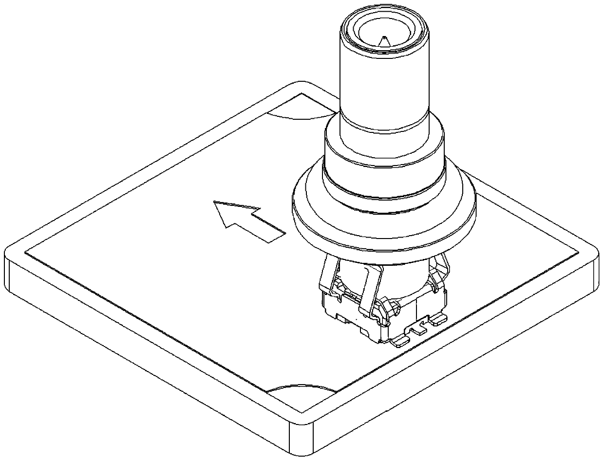
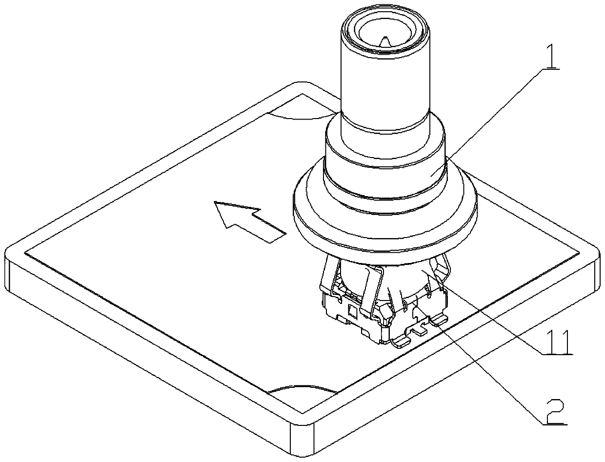
[0025] Below in conjunction with specific embodiment, content of the present invention is described in further detail, figure 2 It shows an assembly diagram of the coaxial connector with shielding function in the present invention, the male seat part 1 is inserted into the female seat part 2, so as to realize the transmission of electric energy or signal. The m...


PUM


Abstract

The invention relates to a coaxial connector with a shielding function. The coaxial connector is formed by mutual insertion and butt joint of a male socket part and a female socket part, wherein the male socket part comprises a male socket shell; the female socket part comprises a female socket insulator, a female socket cover, a female socket terminal and a shielding shell; the shielding shell wraps the peripheral side wall of the female socket insulator; the front side wall and the rear side wall of the shielding shell extend upwards to respectively form a front elastic shielding arm and a rear elastic shielding arm; and the front elastic shielding arm and the rear elastic shielding arm are twisted for a preset angle around respective center lines. Therefore, the influence of external electromagnetic interference on the signal transmission process can be effectively reduced, and the coaxial connector has excellent high-frequency performance. Moreover, more importantly, through the torsion design of each elastic shielding arm, the reliability and stability of the contact between each elastic shielding arm and the outer side wall of the male socket shell are indirectly ensured, andthe good shielding performance of the coaxial connector is further ensured.

Description

technical field [0001] The invention relates to the technical field of electrical connectors, in particular to a coaxial connector with a shielding function. Background technique [0002] With the development of electronic component technology, its size tends to be more and more miniaturized and modularized, which puts forward higher requirements for its assembly reliability and transmission stability. Coaxial connectors are connector products with strong transmission power among the current connector product types, and are widely used in power systems, communication networks, financial manufacturing, elevators, industrial automation, medical equipment, office equipment, home appliances, military manufacturing and other industries. [0003] Coaxial connectors generally include male and female receptacles that mate with each other. Generally speaking, in order to improve the shielding of the electrical connector itself, a shielding shell (such as figure 1 shown in ), but th...

Claims


Application Information

Patent Timeline
IPC IPC(8): H01R24/40H01R13/6581H01R13/6583
CPCH01R13/6581H01R13/6583H01R24/40
Inventor 余开刚何志刚陈进嵩
Owner GOLDENCONN ELECTRONICS TECH CO LTD
Why Eureka
Try Eureka