
A method for manufacture a shield structure in a ribbon-shaped radio frequency transmission line/microstrip radio frequency transmission line

A technology of radio frequency transmission and shielding structure, applied in the fields of magnetic/electric field shielding, waveguide type devices, electrical components, etc., can solve the problems of transmission line interference, inability to achieve the shielding performance of coaxial lines, etc., and achieve the effect of improving shielding performance and preventing leakage

Active Publication Date: 2018-12-18
SHENZHEN SUNWAY COMM
View PDF7 Cites 0 Cited by
  • Summary
  • Abstract
  • Description
  • Claims
  • Application Information

AI Technical Summary

Problems solved by technology

Limited to thinner and lighter terminal products, more and more radio frequency transmission methods are converted from coaxial cables to ribbon feeders. On the one hand, ribbon feeders can achieve the same low loss as coaxial cables, and on the other hand, they can integrate all-in-one transmission lines , can also achieve thinning, but the existing ribbon feeder for transmitting radio frequency signals cannot achieve the shielding performance of coaxial lines because of its completely open sides
[0004] In the future, the integration of 5G terminal products will become higher and higher, and the number and operating frequency of antennas will also reach millimeter waves. This will inevitably put forward higher requirements for the shielding performance of transmission lines, so as to ensure that the external radiation of transmission lines will not affect the normal operation of antennas or other devices. Work, the radiation of the same antenna or other devices will also cause great interference to the transmission line itself

Method used


Image

  • A method for manufacture a shield structure in a ribbon-shaped radio frequency transmission line/microstrip radio frequency transmission line
  • A method for manufacture a shield structure in a ribbon-shaped radio frequency transmission line/microstrip radio frequency transmission line
  • A method for manufacture a shield structure in a ribbon-shaped radio frequency transmission line/microstrip radio frequency transmission line

Examples


Embodiment 1

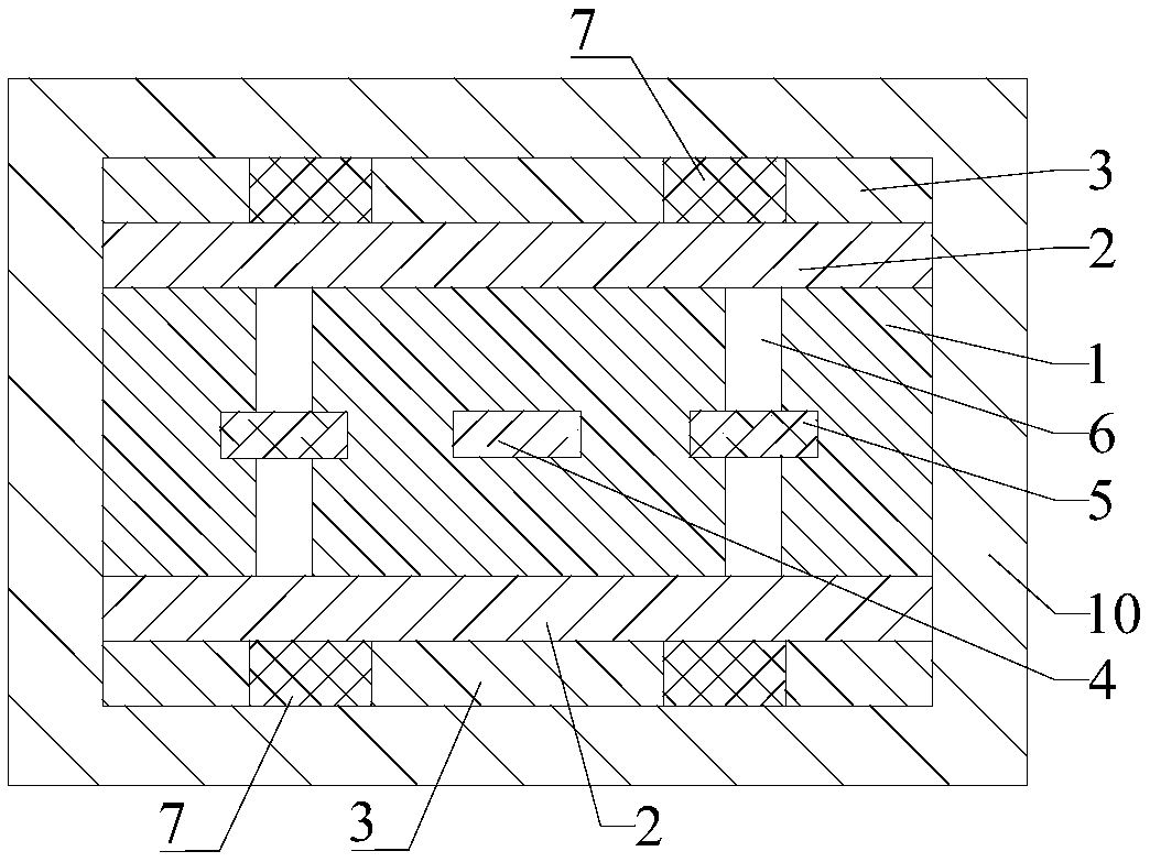
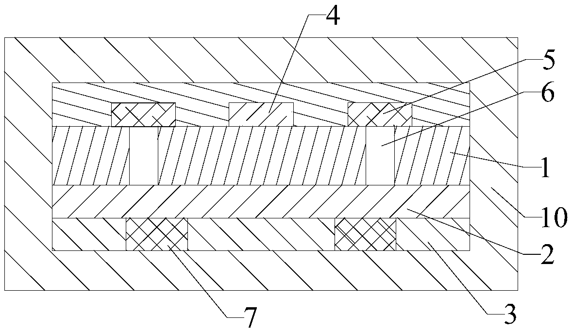
[0052] Please refer to Figure 1 to Figure 3 , Embodiment 1 of the present invention is: the strip radio frequency transmission line / microstrip radio frequency transmission line includes a base material layer 1, at least one side of the base material layer 1 is provided with a system formation 2, and the system formation 2 is far away from the base material One side of the layer 1 is provided with a protective layer 3, and the base material layer 1 is provided with a signal line 4. Optionally, the base material layer 1 is also provided with a ground wire 5 conducting with the system ground layer 2. ; Optionally, the ground wire 5 is connected to the system formation 2 through a ground hole 6 .

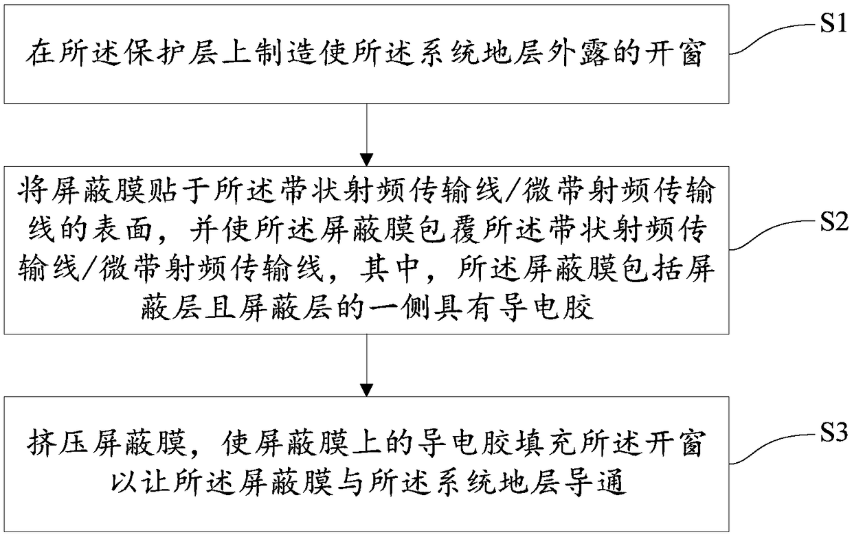
[0053] A method for manufacturing a shielding structure in a strip radio frequency transmission line / microstrip radio frequency transmission line, comprising the following steps,

[0054]S1: Making a window 7 on the protective layer 3 to expose the systematic formation 2;

[0055] S2...

Embodiment 2

[0064] Please refer to figure 1 , Figure 4 and Figure 5 , Embodiment 2 of the present invention is: the strip radio frequency transmission line / microstrip radio frequency transmission line includes a base material layer 1, at least one side of the base material layer 1 is provided with a system formation 2, and the system formation 2 is far away from the base material One side of the layer 1 is provided with a protective layer 3, and the base material layer 1 is provided with a signal line 4. Optionally, the base material layer 1 is also provided with a ground wire 5 conducting with the system ground layer 2. ; Optionally, the ground wire 5 is connected to the system formation 2 through a ground hole 6 .

[0065] A method for manufacturing a shielding structure in a strip radio frequency transmission line / microstrip radio frequency transmission line, comprising the following steps,

[0066] S1: Making a window 7 on the protective layer 3 to expose the systematic formation...

Embodiment 3

[0077] Please refer to figure 1 , Image 6 and Figure 7 , the third embodiment of the present invention is: the strip radio frequency transmission line / microstrip radio frequency transmission line includes a substrate layer 1, at least one side of the substrate layer 1 is provided with a system formation 2, and the system formation 2 is far away from the substrate One side of the layer 1 is provided with a protective layer 3, and the base material layer 1 is provided with a signal line 4. Optionally, the base material layer 1 is also provided with a ground wire 5 conducting with the system ground layer 2. ; Optionally, the ground wire 5 is connected to the system formation 2 through a ground hole 6 .

[0078] A method for manufacturing a shielding structure in a strip radio frequency transmission line / microstrip radio frequency transmission line, comprising the following steps,

[0079] S1: Making a window 7 on the protective layer 3 to expose the systematic formation 2; ...


PUM


Abstract

A method for manufacture a shield structure in a ribbon-shaped radio frequency transmission line / microstrip radio frequency transmission line is disclosed. The strip-shaped radio frequency transmission line / microstrip radio frequency transmission line comprises a substrate layer, at least one side of the substrate layer is provided with a system layer, and a protective layer is arranged on the side of the system layer far from the substrate layer. The system layer comprises the following steps: S1, manufacturing a window on the protective layer to expose the system layer; 2, adhere a shieldingfilm on that surface of the strip-shaped radio frequency transmission line / microstrip radio frequency transmission line and coating the shield film on the strip-shaped radio frequency transmission line / microstrip radio frequency transmission line, wherein the shielding film comprises a shielding lay and one side of the shielding layer is provided with a conductive adhesive; S3: Squeeze the shielding film so that the conductive adhesive on the shielding film fills the window so that the shielding film is in communication with the system formation. A complete and enclosed shielding structure isformed, which greatly improves the shielding performance of the band-shaped RF transmission line / microstrip RF transmission line.

Description

technical field [0001] The invention relates to a strip radio frequency transmission line / microstrip radio frequency transmission line, in particular to a method for manufacturing a shielding structure in a strip radio frequency transmission line / microstrip radio frequency transmission line. Background technique [0002] With the rapid development of mobile communication technology, the current 4G network, mobile Internet has shown explosive growth in both the number of users and the transmission rate. The number of global mobile users has reached more than 3 billion, and the transmission rate of 4G network has reached 100 Mbps. The commercial use of 5G networks, the number of tens of billions of network connections, the low latency of ms levels, and the transmission rate of Gbps will soon become a reality. [0003] Terminal products need to adopt MIMO multi-channel technology to achieve high-speed transmission. Limited to thinner and lighter terminal products, more and mor...

Claims


Application Information

Patent Timeline
IPC IPC(8): H05K9/00H01P11/00
CPCH01P11/003H05K9/0056
Inventor 张昕曹艳杰陈少波徐颖龙虞成城
Owner SHENZHEN SUNWAY COMM
Learn More