Waste thick cable stripping device

A cable and waste technology, which is applied in the field of waste and thick cable stripping devices, can solve the problems of manual refilling, high labor intensity, and low stripping efficiency, and achieve the effects of improving stripping efficiency, reducing labor intensity, and improving stripping effect

Pending Publication Date: 2020-06-09
新晃银龙新能源有限公司
0 Cites 3 Cited by

AI-Extracted Technical Summary

Problems solved by technology

[0005] Aiming at the deficiencies of the prior art, the present invention provides a waste and old thick cable stripping device, which solves the problems that the existing waste...

Method used

Described cutting knife 83 is set to the right-angled triangle that contains 30 ° of included angles, and this cutting knife 83 is provided with 3-4, is evenly distributed in the inside of cylinder tube 82, can increase the depth of waste and old cable step by step, will The sheath of the waste cable is cut, which improves the stripping effect.
Described wire mechanism 7 comprises fixed seat 71, fork 72 and ring 73, and described fixed seat 71 is welded on the side of frame body 1; Described fork 72 is set to L shape, and this The bottom of the swing rod 72 is connected with the fixed seat 71 by a pin shaft, and the top of the swing rod 72 is w...

Abstract

The invention discloses a waste thick cable stripping device. The device comprises a rack body, a side vertical plate, a top plate, an electronic speed regulator, a motor base, a transmission mechanism, a wire guiding mechanism and a wire stripping mechanism. Through the arrangement of the transmission mechanism, when a waste cable is stripped, the adjustable-speed motor drives a bevel gear set torotate through the transmission shaft, and a feeding wheel is driven to rotate through the rotating shaft under the cooperation of the gear set, so that the waste cable is conveyed, the labor intensity of workers is effectively reduced, and the stripping efficiency of the waste cable is improved; by arranging cutting knives, each cutting knife is arranged to be a right triangle with a 30-degree included angle, the number of the cutting knives is 3-4, the cutting knives are evenly distributed in the cylinder. The depth of the waste cable can be increased step by step, the sheath of the waste cable is cut, and the wire stripping effect is improved.

Application Domain

Technology Topic

Image

  • Waste thick cable stripping device
  • Waste thick cable stripping device
  • Waste thick cable stripping device

Examples

  • Experimental program(1)

Example Embodiment

[0028] Example
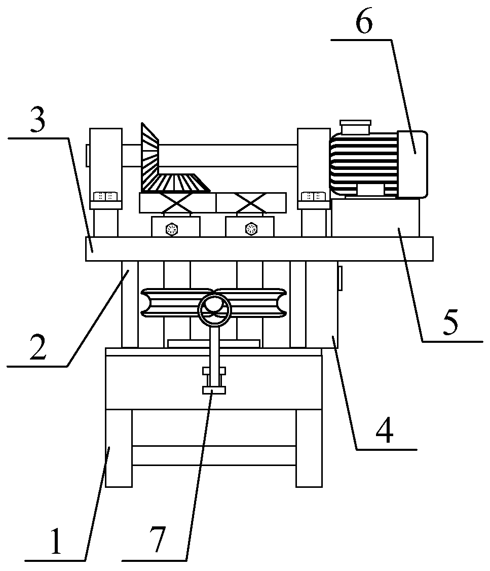
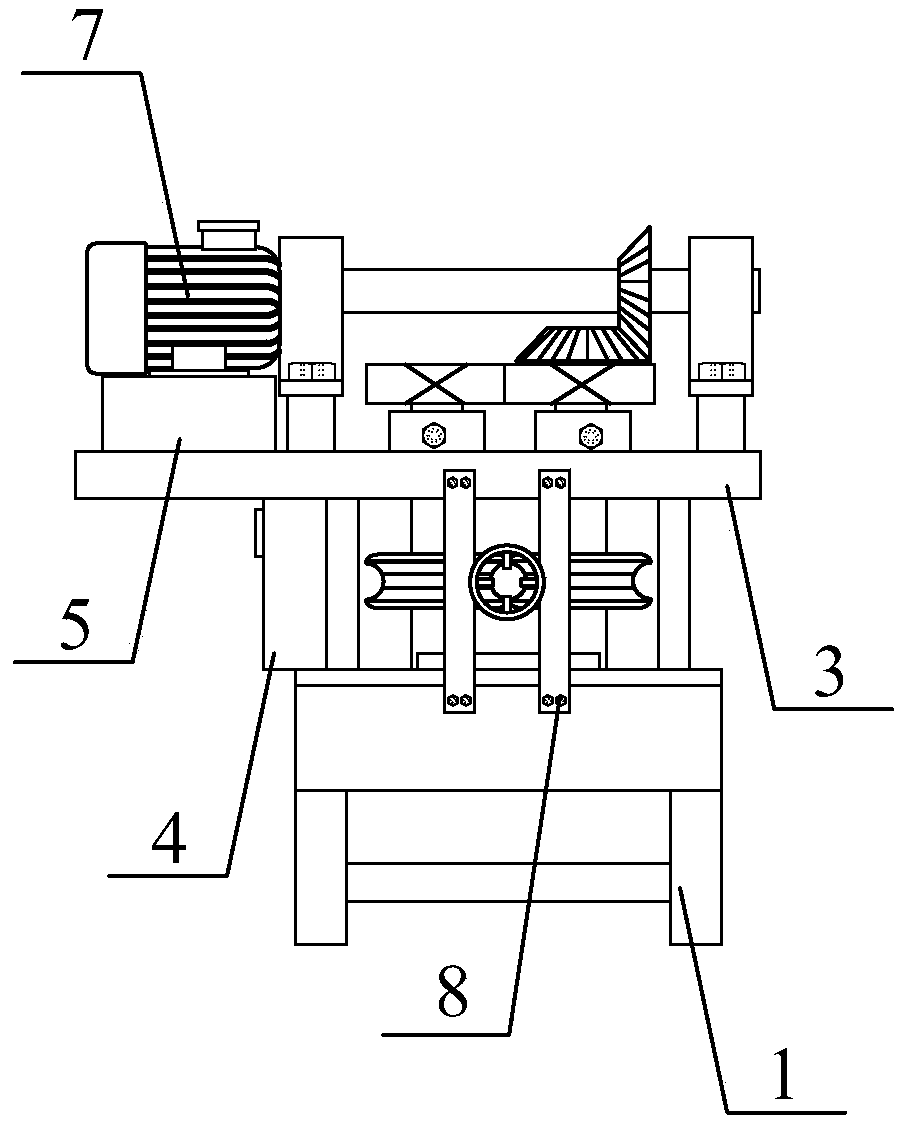
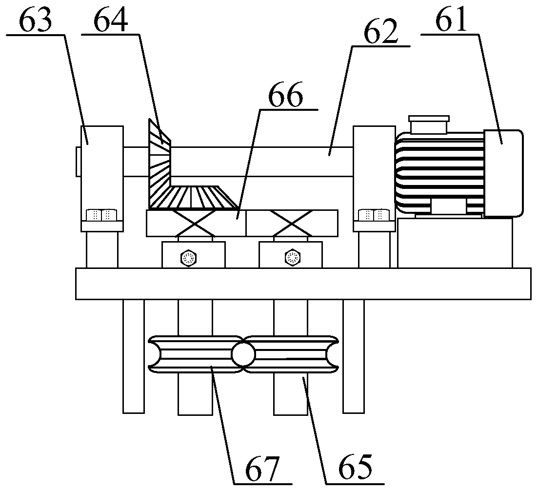
[0029] Such as Figure 1-6 As shown, the present invention provides a technical solution: a waste and thick cable stripping device, including a frame body 1, a side vertical plate 2, a top plate 3, an electronic speed controller 4, a motor seat 5, a transmission mechanism 6, and a wire mechanism 7. And stripping mechanism 8, the two side vertical plates 2 are respectively welded on both sides of the top of the frame body 1; the top plate 3 is installed on the top of the side vertical plate 2 by bolts; the electronic adjustment The speed controller 4 is installed on one side of the side vertical plate 2 by bolts; the motor seat 5 is fixed above one end of the top plate 3; the peeling mechanism 6 is detachably connected to the frame body 1 and the top plate 3; The wire mechanism 7 is welded on one side of the frame body 1; the wire stripping mechanism 8 is arranged on the opposite side of the wire mechanism 7 and is fixed with the frame body 1 by bolts.
[0030] The transmission mechanism 6 includes a speed regulating motor 61, a transmission shaft 62, a seated bearing 63, a bevel gear set 64, a rotating shaft 65, a gear set 66 and a feed wheel 67, and the speed regulating motor 61 is mounted on the motor seat by bolts. 5, the speed-regulating motor 61 and the transmission shaft 62 are connected by a coupling; the two ends of the transmission shaft 62 are matedly connected with the seated bearing 63; the said seated bearing 63 adopts two, all of which are installed by bolts The top plate 3; the bevel gear set 64 is composed of two bevel gears, the bevel gear set 64 is respectively connected with the transmission shaft 62 and the rotating shaft 65 in interference fit; the two rotating shafts 65 are arranged in parallel, the The two ends of the rotating shaft 65 are respectively connected with the frame body 1 and the top plate 3 through bearings; the gear set 66 is composed of two spur gears, which are fitted on the top of the rotating shaft 65 and meshed with each other; the feeding wheel 67 Two are used, and both are installed in the middle of the rotating shaft 65. When the waste cable is stripped, the speed-regulating motor 61 drives the bevel gear set 64 through the drive shaft 62 to rotate, and with the cooperation of the gear set 66 drives the feed wheel 67 through the rotating shaft 65 Rotation will realize the transportation of waste cables, effectively reduce the labor intensity of manpower, and improve the stripping efficiency of waste cables.
[0031] The feeding wheel 67 is arranged in a waist shape, which can clamp and transmit the waste cables and ensure the conveying effect.
[0032] The wire mechanism 7 includes a fixed seat 71, a swing rod 72, and a ring 73. The fixed seat 71 is welded to one side of the frame body 1; the swing rod 72 is arranged in an L shape. The bottom of the shaft is connected with the fixed seat 71 by a pin shaft, and the top of the pendulum rod 72 is welded with a ring 73. The pendulum rod 72 has enough space for movement, which can adapt to the conveying of bent cables to prevent the belt from being bent during the conveying of waste cables. There is a jam.
[0033] The wire stripping mechanism 8 includes a fixed plate 81, a cylindrical barrel 82 and a cutting knife 83. The fixed plate 81 uses two; the cylindrical barrel 82 is welded between the fixed plate 81 and the fixed plate 81. 82 is the same height as the waistline of the feed wheel 67; the cutting knife 83 is welded in the cylindrical barrel 82, and the waste cable enters the cylindrical barrel 82 under the conveying mechanism 6, and the cutting knife 83 cuts the waste cable.
[0034] The cutting knife 83 is set as a right triangle with an included angle of 30°. There are 3-4 cutting knives 83, which are evenly distributed inside the cylindrical barrel 82, which can gradually increase the depth of the waste cable and remove the waste cable. The outer skin is cut to improve the stripping effect.
[0035] working principle
[0036] In use, when the waste cable is stripped, the speed-regulating motor 61 drives the bevel gear set 64 to rotate through the drive shaft 62, and with the cooperation of the gear set 66, drives the feed wheel 67 to rotate through the rotating shaft 65, which will realize the transportation of the waste cable. Under the transportation of the transmission mechanism 6, the waste cable enters the cylinder 82, and the cutting knife 83 cuts the waste cable. The cutting knife 83 is set as a right triangle with an included angle of 30°. The cutting knife 83 is set with 3-4, uniformly distributed. Inside the cylinder 82, the depth of the waste cable can be gradually increased, the outer skin of the waste cable can be cut, and the stripping effect can be improved. The swing rod 72 has enough space for movement, which can adapt to the conveying of the bent cable and prevent When the waste cable is conveyed, it is jammed due to bending.
[0037] In summary, the waste and thick cable stripping device is provided with frame body 1, side vertical plate 2, top plate 3, electronic speed controller 4, motor seat 5, and transmission mechanism 6, which solves the existing waste and thick cable During the peeling process, manual feeding and direction control are required, which is labor-intensive and the peeling efficiency is low.

PUM

no PUM

Description & Claims & Application Information

We can also present the details of the Description, Claims and Application information to help users get a comprehensive understanding of the technical details of the patent, such as background art, summary of invention, brief description of drawings, description of embodiments, and other original content. On the other hand, users can also determine the specific scope of protection of the technology through the list of claims; as well as understand the changes in the life cycle of the technology with the presentation of the patent timeline. Login to view more.

Similar technology patents

Classification and recommendation of technical efficacy words

  • Reduce manual labor intensity
  • Improve peeling efficiency

Gorgon fruit husking machine

Owner:安徽济善堂中药科技有限公司
Why Eureka
Try Eureka