
Camera module and terminal equipment

A technology of camera module and terminal equipment, which is applied in the field of cameras, can solve problems such as camera running out of focus, unclear pictures taken by customers, UV glue penetration, etc., to reduce the defective rate of production and assembly, reduce the processing process, and reduce production costs low effect

Pending Publication Date: 2020-06-09
重庆市天实精工科技有限公司
View PDF0 Cites 0 Cited by
  • Summary
  • Abstract
  • Description
  • Claims
  • Application Information

AI Technical Summary

Problems solved by technology

[0003] (1) Lens and motor focus lock: there will be scratches, dirt and other defective products during the focus lock process;
[0004] (2) Dispensing UV glue: there is leakage of dispensing glue flowing out of the client camera and the focus is not clear, resulting in defective products;
[0005] (3) UV irradiation: Leaked irradiation causes UV glue to penetrate into the module, resulting in unclear photos taken by customers or shadows leading to defective products

Method used


Image

  • Camera module and terminal equipment

Examples


Embodiment Construction

[0023] Below in conjunction with accompanying drawing this is further described.

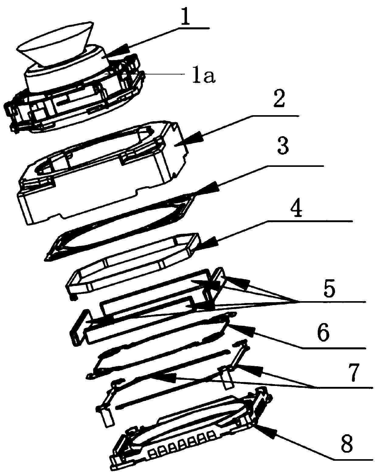
[0024] Such as figure 1 As shown, in this embodiment, a camera module includes a lens 1, a motor housing 2, a motor upper shrapnel 3, a drive coil 4, a drive magnet group 5, a motor lower shrapnel 6, a motor PIN terminal 7 and a motor base 8 , the connection relationship of the above components is as follows:

[0025] The lens 1 is fitted in the motor housing 2 so that it can move up and down. The elastic piece 3 on the motor is arranged between the stepped surface 1 a in the middle of the lens 1 and the inner top wall of the motor housing 2 , and the elastic piece 3 on the motor is connected to the lens 1 and the motor housing 2 respectively. The driving coil 4 is wound on the lens 1, and the driving coil 4 is used for electrical connection with the control circuit board; the control circuit board controls the driving current input to the driving coil 4 to control the driving magnet group 5 a...


PUM


Abstract

The invention discloses a camera module and terminal equipment. The camera module comprises a lens, a motor shell, a motor upper elastic sheet, a driving coil, a driving magnet group, a motor lower elastic sheet, a motor PIN terminal and a motor base. The driving magnet group is fixedly arranged on the inner side wall of the motor shell; the motor PIN terminal is arranged on the motor base; the bottom opening of the motor shell is connected with the motor base in a clamping or welding or bonding manner; the lens can be matched in the motor shell in an up-and-down moving manner; the motor upperelastic sheet is arranged between the step surface in the middle of the lens and the inner top wall of the motor shell, and the motor upper elastic sheet is respectively connected with the lens and the motor shell; the driving coil is wound on the lens; and the motor lower elastic sheet is arranged between the bottom of the lens and the motor base. According to the invention, the processing technological process can be reduced, and the production cost and the production assembly reject ratio can be reduced.

Description

technical field [0001] The invention belongs to the technical field of cameras, and in particular relates to a camera module and terminal equipment. Background technique [0002] With the improvement of the degree of automation, the existing processing technology is required to be continuously improved towards automation, and in order to meet the survival of enterprises, the existing enterprises are required to move towards simplification of processing technology, generalization of materials, generalization of equipment, less manpower demand, and production Keep moving forward with low cost. In the existing camera industry, the lens and motor are designed in a split structure, which requires technological processes such as focusing and locking the lens and motor, spotting UV glue for fixing, and UV irradiation. Due to the complex process, and each process link is prone to produce defective products, such as: [0003] (1) Lens and motor focus lock: there will be scratches, ...

Claims


Application Information

Patent Timeline
Patent Type & Authority Applications(China)
IPC IPC(8): H04N5/225
CPCH04N23/54H04N23/50H04N23/57H04N23/55
Inventor 罗卿赵军邓小光卢江齐书李廷飞晏政波蒋鑫宇
Owner 重庆市天实精工科技有限公司
Learn More