Check patentability & draft patents in minutes with Patsnap Eureka AI!

Dimmer polarity correction circuit

A technology of polarity correction and dimmer, which is applied in the direction of light source, electric light source, electrical components, etc., can solve the problems that it is difficult to ensure the installation of LED lamps and consume a lot of time, and achieve simple design, improved efficiency, and increased cost Effect

Active Publication Date: 2020-06-09
XIAMEN PVTECH CO LTD
View PDF5 Cites 0 Cited by
  • Summary
  • Abstract
  • Description
  • Claims
  • Application Information

AI Technical Summary

Problems solved by technology

[0003] However, when technicians need to install a large number of LED lamps, it is difficult to ensure that all LED lamps are installed correctly
If there are N LED lights connected in parallel and one of the LED lights is connected to the wrong polarity of the dimmer, technicians need to check each LED light one by one, which will consume a lot of time

Method used


Image

  • Dimmer polarity correction circuit
  • Dimmer polarity correction circuit
  • Dimmer polarity correction circuit

Examples


Embodiment Construction

[0035] The embodiments of the dimmer polarity correction circuit provided by the present invention will be described below with reference to related drawings. For the sake of clarity and convenience of illustration, the dimensions and proportions of the components in the drawings may be exaggerated or reduced. . In the following description and / or claims, when a component is referred to as being "connected" or "coupled" to another component, it may be directly connected or coupled to the other component or there may be intervening components; and when a component is referred to as " When "directly connected" or "directly coupled" to another component, there are no intervening components, and other words used to describe the relationship between components or layers should be interpreted in the same way. To facilitate understanding, the same components in the following embodiments are described with the same symbols.

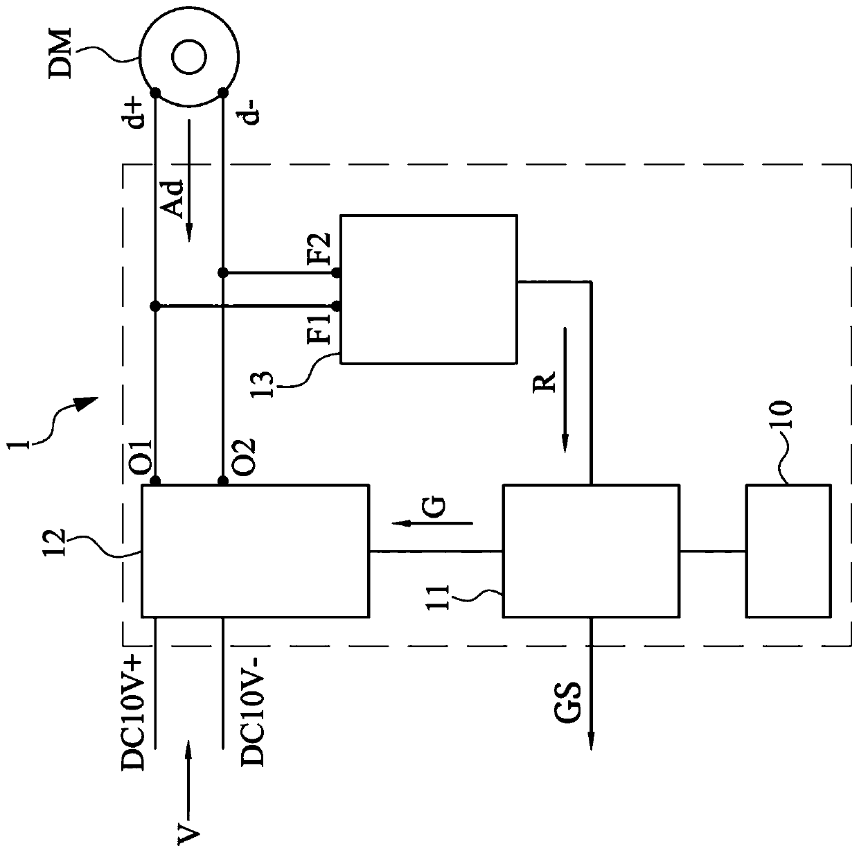
[0036] see figure 1 , which is a block diagram of the dim...


PUM


Abstract

The invention relates to a dimmer polarity correction circuit. The circuit may include a control circuit, an adjustment circuit, and a detection circuit. The adjustment circuit can be connected with the control circuit, a working voltage input end and a dimmer and can comprise a plurality of switches. The adjustment circuit can receive the dimming signal of the dimmer. The detection circuit can beconnected with the dimmer and the control circuit, can detect the dimming signal to generate a reference voltage, and can transmit the reference voltage to the control circuit. The control circuit can keep the on-off states of the switches of the adjustment circuit unchanged or adjust the on-off states of the switches of the adjustment circuit according to the reference voltage.

Description

technical field [0001] The invention relates to a dimmer polarity correction circuit. Background technique [0002] Due to the advancement of technology, the functions of LED lights are becoming more and more powerful, and the manufacturing cost is also getting lower and lower, so they are more widely used. Generally speaking, when installing LED lamps, technicians need to pay special attention to whether the connection polarity of the dimmer connected to the LED lamp is correct, so as to avoid the abnormal operation of the LED lamp. [0003] However, when technicians need to install a large number of LED lamps, it is difficult to ensure that all LED lamps are correctly installed. If there are N LED lamps connected in parallel and one of the LED lamps is connected to the wrong polarity of the dimmer, technicians need to check each LED lamp one by one, which will consume a lot of time. Contents of the invention [0004] The invention provides a dimmer polarity correction ...

Claims


Application Information

Patent Timeline
Patent Type & Authority Applications(China)
IPC IPC(8): H05B45/00
CPCH05B44/00H05B45/10H05B45/31H05B45/14H05B45/325
Inventor 卢福星刘荣土
Owner XIAMEN PVTECH CO LTD
Features
  • R&D
  • Intellectual Property
  • Life Sciences
  • Materials
  • Tech Scout
  • Unparalleled Data Quality
  • Higher Quality Content
  • 60% Fewer Hallucinations
Learn More