
Remote control emergency brake valve for railway propulsion vehicle

An emergency braking and vehicle technology, which is applied in the railway braking system, the operating mechanism of the railway vehicle brake, railway car body parts, etc., can solve the inconvenience of detecting the surrounding conditions of the vehicle, easily distracting the attention of the workers, and the inability to realize emergency parking and other issues to achieve the effect of promoting safe development, ensuring safety and high practicability

Pending Publication Date: 2020-06-12
陕西榆横铁路有限责任公司
View PDF0 Cites 0 Cited by
  • Summary
  • Abstract
  • Description
  • Claims
  • Application Information

AI Technical Summary

Problems solved by technology

[0004] Because the existing simple emergency brake valve is in use, the operator needs to always hold the manual pull rope of the simple brake valve, and at the same time must look around and pay attention to the situation around the vehicle, which is not convenient for the operator to accurately and timely detect the surrounding conditions of the vehicle , and it is easy to distract the attention of the operators, and the operation is inconvenient, which may easily cause the situation that the emergency stop cannot be realized in an emergency

Method used


Image

  • Remote control emergency brake valve for railway propulsion vehicle
  • Remote control emergency brake valve for railway propulsion vehicle
  • Remote control emergency brake valve for railway propulsion vehicle

Examples


Embodiment Construction

[0032] In order to make the purpose, technical solutions and advantages of the embodiments of the present invention clearer, the technical solutions of the present invention will be clearly and completely described below in conjunction with the accompanying drawings. Obviously, the described embodiments are part of the embodiments of the present invention, not all of them. the embodiment. Based on the embodiments of the present invention, all other embodiments obtained by persons of ordinary skill in the art without making creative efforts belong to the protection scope of the present invention.

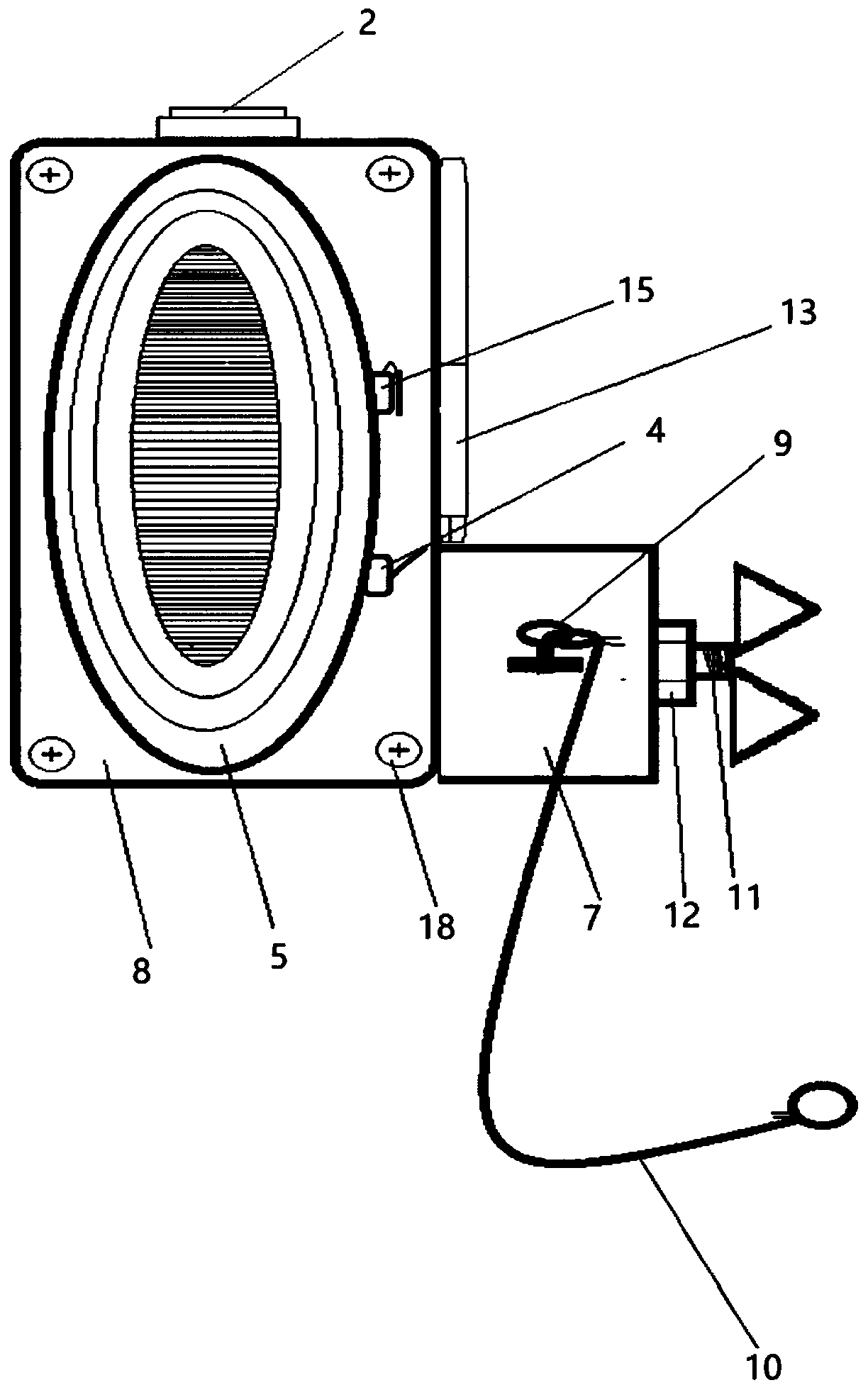
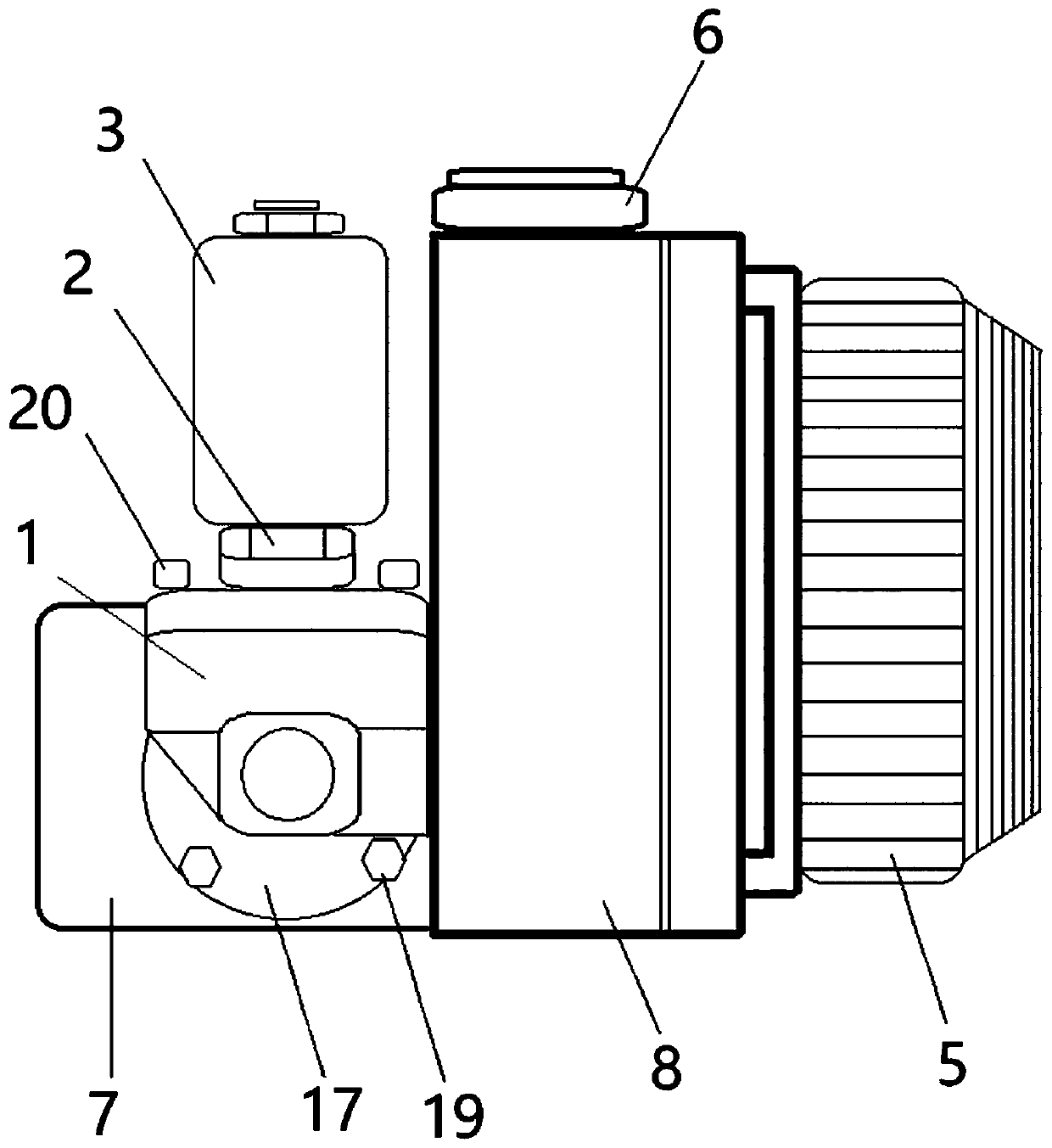
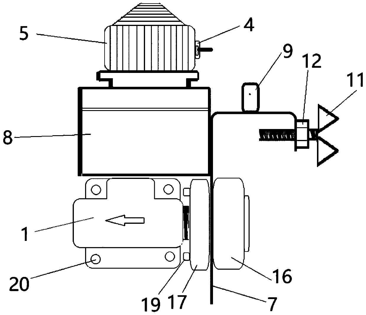
[0033] As a specific embodiment of the present invention, in combination with Figure 1 to Figure 6 As shown, a remote control emergency brake valve for railway propulsion vehicles includes a valve body 1, a valve core 2, a coil 3, a power switch 4, a warning light 5, a buzzer 6, a fixed bracket 7, an electrical protection cover 8, a control Circuit board, relay and power supply, in...


PUM


Abstract

The invention discloses a remote control emergency brake valve for a railway propulsion vehicle. The remote control emergency brake valve comprises a valve body, a valve element, a coil, a control circuit board, a relay and a power source, an air duct penetrating through the two ends is formed in the valve body, one end of the air duct is used for being connected with a train main air pipe, and the other end of the air duct is used for exhausting air; the power supply is electrically connected with the control circuit board, the control circuit board is electrically connected with the relay, and the relay is electrically connected with the coil; and the coil is arranged on the upper end face of the valve body, one end of the valve element penetrates through the coil and extends into the air duct from the upper end face of the valve body to seal the air duct, one end of the valve element extends out of the coil, and when the coil is powered on, the coil can drive the valve element to move upwards to open the air duct. The control circuit board is used for receiving a control signal transmitted by the remote controller, controlling the relay to be closed according to the control signal and further controlling the coil to be powered on or off. The remote control emergency brake valve is convenient to operate, potential safety hazards are reduced, shunting operation safety and personal safety are guaranteed, safe development of companies is promoted, and great economic benefits are achieved.

Description

technical field [0001] The invention belongs to the technical field of railway train braking devices, and in particular relates to a remote-controlled emergency brake valve for railway propulsion vehicles. Background technique [0002] The emergency brake valve is an indispensable equipment for the safe operation of the railway. The function of the emergency brake valve is to force the running train to take emergency brake. In the railway shunting operation, the correct and timely use of the simple brake valve can ensure the operation and personal safety, and the use of the emergency brake valve can avoid safety accidents caused by emergencies. [0003] The existing simple emergency brake valve is composed of a valve body, a valve stem and a pull rope. , When it is found that the driving and personal safety are endangered, a simple emergency brake valve should be used. Specifically, in case of an emergency during operation, which endangers traffic and personal safety, and ...

Claims


Application Information

Patent Timeline
Patent Type & Authority Applications(China)
IPC IPC(8): B61H13/00B61H11/10
CPCB61H11/10B61H13/00
Inventor 冯斌孙林峰唐飞李宝金闫龙
Owner 陕西榆横铁路有限责任公司
Learn More