Automatic telescopic lantern and using method thereof

An automatic telescopic and lantern technology, which is applied in the direction of lampshades, lighting and heating equipment, semiconductor devices of light-emitting elements, etc., can solve the problems of inability to realize automatic control, easy to ignite the outer shell of the lantern, and short ignition time, so as to reduce energy consumption , save labor costs, and facilitate storage and transportation

Inactive Publication Date: 2020-06-12
SHENZHEN WINS ELECTRONIC TECH CO LTD
View PDF2 Cites 2 Cited by
  • Summary
  • Abstract
  • Description
  • Claims
  • Application Information

AI Technical Summary

Problems solved by technology

When using this patent, it is necessary to exert force on the upper cloud body and two support rods. When the upper cloud body is stuck in the two slots, the lantern will open; when the upper cloud body is out of the two slots, the lantern will be folded into a cylindrical , the size of the lantern is reduced. Although the lantern can be retracted and retracted, it still needs manual force to adjust the lantern. The labor cost is high and automatic control cannot be realized.
[0006] The light source in early lanterns was lighted candles or oil lamps, which had the problem of short lighting time and were easy to ignite the outer shell of the lantern, so the safety was low
Nowadays, people often install a lamp holder in the middle of the lantern, such as a light bulb or a lamp tube, and connect it to a power source as the light source of the lantern; however, incandescent bulbs and energy-saving lamp tubes generate more heat and consume more power when they are lit.

Method used


Image

  • Automatic telescopic lantern and using method thereof
  • Automatic telescopic lantern and using method thereof
  • Automatic telescopic lantern and using method thereof

Examples


Embodiment 1

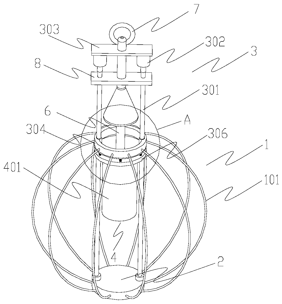
[0052] as attached figure 1 As shown, an automatically telescopic cage body 1 includes a cage body 1 , a bottom support 2 , a sliding assembly 3 and a lighting assembly 4 .

[0053] The base bracket 2 is arranged at the lower end of the cage body 1 , the sliding assembly 3 is arranged at the upper end of the cage body 1 , and the lighting assembly 4 is arranged inside the cage body 1 .

[0054] The cage body 1 includes a plurality of steel wire ropes 101, and the outer side of the cage body 1 is wrapped with elastic cloth, and the surface of the elastic cloth is provided with a waterproof layer and has light transmission.

[0055] The sliding assembly 3 includes a set of ball screws 301 , a driving motor 302 , and a slip ring 304 .

[0056] One end of the ball screw 301 is in transmission connection with the drive motor 302 , and the other end is fixedly connected with the bottom bracket 2 through a bearing.

[0057] A group of ball screws 301 are respectively arranged on bo...

Embodiment 2

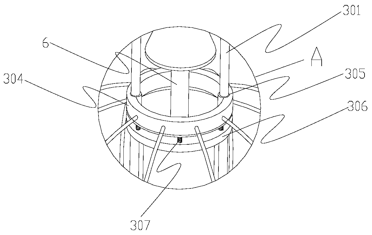
[0080] Based on the above-mentioned embodiment 1, the similarities will not be repeated, and the difference is that, as attached Figure 6 As mentioned above, one end of the ball screw 301 is in transmission connection with the driving motor 302 , and the other end is fixedly connected with the limiting plate 306 through a bearing.

[0081] The limiting plate 306 is fixedly connected to the bottom support 2 through a connecting rod 5 .

Embodiment 3

[0083] Based on the above-mentioned embodiment 1 or 2, a method for using an automatic telescopic lantern comprises the following steps:

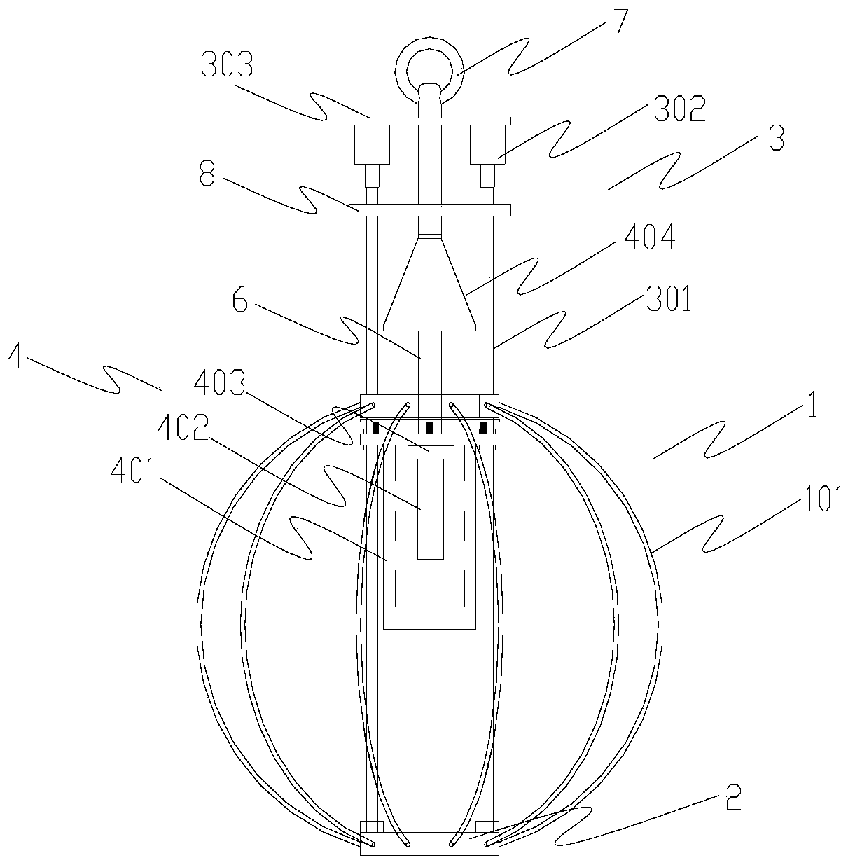
[0084] 101. During festivals, unfold the cage body 1, turn on the driving motor 302, the driving motor 302 drives the ball screw 301 to rotate, the ball screw 301 drives the screw nut 305 to slide, the screw nut 305 drives the slip ring 304 to move, and the slip ring 304 drives The arc of the steel wire rope 101 changes until the slip ring 304 is close to the limit plate 306, and the cage body 1 is unfolded and formed;

[0085] 102. After completing step 101, turn on the lighting assembly 4, turn on the power supply of the LED lamp 402, and illuminate the cage body 1;

[0086] 103. Turn off the lighting assembly 4, turn off the power supply of the LED lamp 402, and turn off the lighting of the cage body 1;

[0087] 104. Repeat steps 102-103 to complete the lighting use of the cage body 1 during the festival;

[0088] 105. After the festiv...


PUM


Abstract

The invention relates to an automatic telescopic lantern and a using method thereof. The automatic telescopic lantern comprises a lantern body, a bottom support, a sliding assembly and a lighting assembly. The bottom support is arranged at the lower end of the cage body, the sliding assembly is arranged at the upper end of the cage body, and the lighting assembly is arranged in the cage body. Thecage body comprises a plurality of steel wire ropes, and the outer side of the cage body is wrapped with elastic cloth. The use method is simple to operate and convenient to use; the lantern mainly overcomes the defects that a traditional lantern is troublesome to assemble and disassemble, time-consuming, labor-consuming and the like, the lantern provided is simple in structure, can achieve automatic contraction, can be unfolded when used in festivals, can be folded when not used in non-festivals, is convenient to use, saves the labor cost during assembly and disassembly, and is small in mainbody size and convenient to store and transport.

Description

technical field [0001] The invention relates to the technical field of festival decoration, in particular to an automatic retractable lantern and its usage method. Background technique [0002] Chinese lanterns, also collectively referred to as lanterns, are a traditional Chinese folk handicraft. Lanterns originated in the Western Han Dynasty and have a history of more than 2,000 years. They have played an important role in the long history of the Chinese nation. They symbolize the splendor of Chinese civilization and the prosperity of the country. All over my country, on festive days such as festivals or weddings, people hang up red lanterns symbolizing reunion to create a festive atmosphere. [0003] The traditional way of hanging lanterns is to hang them in a unified way before the festival. Workers lift them up through elevators and hang them on street lamps or buildings. Every year, several major festivals will hang them, and then take them down in the same way after ...

Claims


Application Information

Patent Timeline
IPC IPC(8): F21S9/03F21V3/02F21V21/22F21V23/00F21Y115/10
CPCF21S9/035F21V3/02F21V21/22F21V23/023F21Y2115/10
Inventor 赵胜飞
Owner SHENZHEN WINS ELECTRONIC TECH CO LTD
Why Eureka
Try Eureka