Cooling, dehumidifying and desalting device

A technology for cooling, dehumidification, and salt water, applied in the field of electric power, can solve problems such as high cost, short-circuit failure of power equipment, corrosion of power distribution cabinets, etc., and achieve the effect of low cost and simple structure

Inactive Publication Date: 2020-06-12
ELECTRIC POWER RESEARCH INSTITUTE, CHINA SOUTHERN POWER GRID CO LTD +1
View PDF6 Cites 3 Cited by
  • Summary
  • Abstract
  • Description
  • Claims
  • Application Information

AI Technical Summary

Problems solved by technology

[0002] The temperature of the gas in the power equipment cabinet in normal operation is lower than the temperature of the cabinet shell, and when the humidity of the gas in the cabinet reaches a certain value, the top of the cabinet is easy to condense and form water droplets, which will cause short circuit of the power equipment when the water droplets drip down Failure, falling to the bottom will corrode the bottom plate of the power distribution cabinet and make the equipment invalid
The tide driving device in the existing power equipment cabinet is a tide driving heater controlled by a temperature and humidity controller. When the gas temperature in the cabinet is lower than the lower limit temperature set by the temperature and humidity controller, the temperature and humidity controller will start the cabinet The heater in the cabinet is heated, and because the cabinet is a sealed space, the salty air is only heated and not discharged out of the cabinet. When the heater stops working, the salty hot air will still condense into salt water and corrode the cabinet. body
In order to solve the problem of dehumidification and salt spray in the cabinet, an air conditioner can be installed in the cabinet, but the structure of such an arrangement is complicated and the cost is too high

Method used


Image

  • Cooling, dehumidifying and desalting device
  • Cooling, dehumidifying and desalting device
  • Cooling, dehumidifying and desalting device

Examples


Embodiment Construction

[0027] The following will clearly and completely describe the technical solutions in the embodiments of the present invention with reference to the accompanying drawings in the embodiments of the present invention. Obviously, the described embodiments are only some, not all, embodiments of the present invention. Based on the embodiments of the present invention, all other embodiments obtained by persons of ordinary skill in the art without making creative efforts belong to the protection scope of the present invention.

[0028] In order to enable those skilled in the art to better understand the solution of the present invention, the present invention will be further described in detail below in conjunction with the accompanying drawings and specific embodiments.

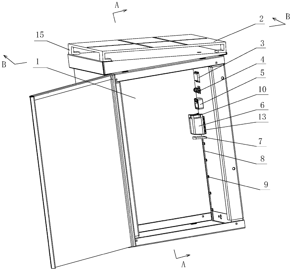
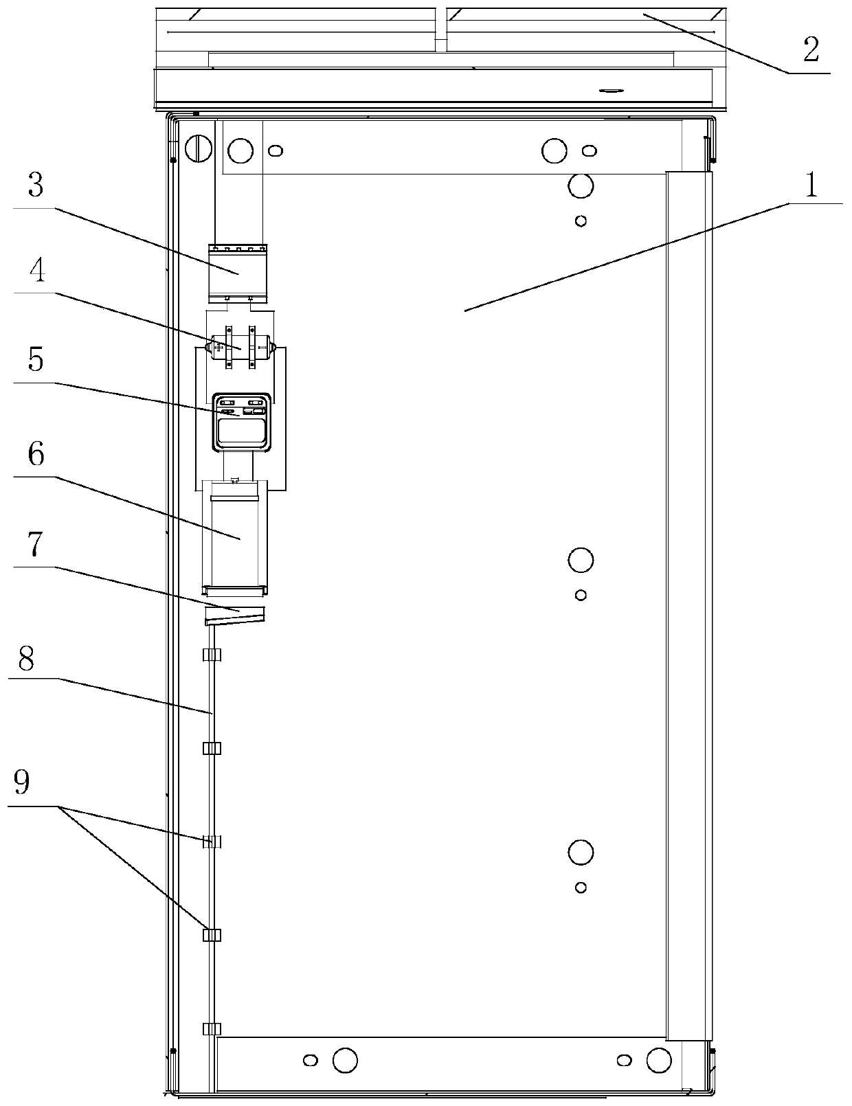
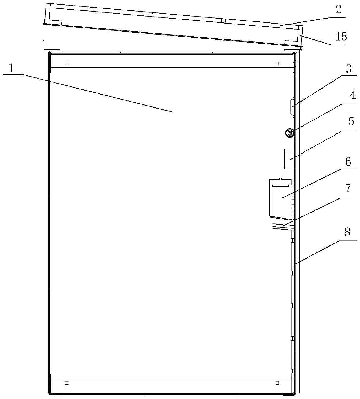
[0029] Please refer to Figure 1 to Figure 5 , figure 1 It is a structural schematic diagram of the present invention, figure 2 for figure 1 A-A sectional view, image 3 for figure 1 The B-B direction sectiona...


PUM


Abstract

The invention provides a cooling, dehumidifying and desalting device. The device comprises an air draft assembly, a cooling assembly, a detection assembly and a water collection assembly. When the detection assembly detects that the air temperature in the power distribution cabinet body rises to a preset temperature, the air draft assembly sucks salt-containing hot air in the power distribution cabinet body into the cooling assembly. The cooling assembly comprises a cooling piece and a heat dissipation body. The cooling piece is used for cooling the radiator. The cooling channel arranged in the radiator condenses the sucked salt-containing hot air into saline water, the water collecting assembly collects the saline water discharged by the cooling channel and discharges the saline water outof the power distribution cabinet body, and compared with the mode that an air conditioner is installed in the power distribution cabinet body to solve the problems of moisture and salt mist in the power distribution cabinet body, the power distribution cabinet is simple in structure and low in cost.

Description

technical field [0001] The invention relates to the field of electric power technology, in particular to a cooling, dehumidification and desalination device. Background technique [0002] The temperature of the gas in the power equipment cabinet in normal operation is lower than the temperature of the cabinet shell, and when the humidity of the gas in the cabinet reaches a certain value, the top of the cabinet is easy to condense and form water droplets, which will cause short circuit of the power equipment when the water droplets drip down If it falls to the bottom, it will corrode the bottom plate of the power distribution cabinet and cause the equipment to fail. The tide driving device in the existing power equipment cabinet is a tide driving heater controlled by a temperature and humidity controller. When the gas temperature in the cabinet is lower than the lower limit temperature set by the temperature and humidity controller, the temperature and humidity controller wil...

Claims


Application Information

Patent Timeline
Patent Type & Authority Applications(China)
IPC IPC(8): H02B1/56H02B1/28H02B1/32H02J7/35H02S20/20
CPCH02B1/565H02B1/28H02B1/32H02S20/20Y02E10/50
Inventor 史训涛柯清派雷金勇袁智勇白浩徐全徐敏郭祚刚谈赢杰黄安迪周长城林跃欢余文辉罗俊平顾衍璋吴争荣汪皓
Owner ELECTRIC POWER RESEARCH INSTITUTE, CHINA SOUTHERN POWER GRID CO LTD
Why Eureka
Try Eureka