Charging pile capable of automatic protection

A technology of automatic protection and charging piles, applied in the direction of collectors, electric vehicles, electrical components, etc., to prevent excessive load and ensure efficiency

Inactive Publication Date: 2020-06-12
DONGYANG PINGZHOU ELECTRIC VEHICLE TECH CO LTD
View PDF0 Cites 1 Cited by
  • Summary
  • Abstract
  • Description
  • Claims
  • Application Information

AI Technical Summary

Problems solved by technology

[0002] If the charging pile is overheated, it is necessary to find a way to let it dissipate heat. Compared with other power sources, the heat dissipation of the charging pile system is much larger, and the requirements for the thermal design of the system are extremely strict. There are currently four commonly used cooling

Method used


Image

  • Charging pile capable of automatic protection
  • Charging pile capable of automatic protection
  • Charging pile capable of automatic protection

Examples


Embodiment Construction

[0018] All features disclosed in this specification, or steps in all methods or processes disclosed, may be combined in any manner, except for mutually exclusive features and / or steps.

[0019] Combine below Figure 1-5 The present invention is described in detail, and for convenience of description, the orientations mentioned below are now stipulated as follows: figure 1 The up, down, left, right, front and back directions of the projection relationship itself are the same.

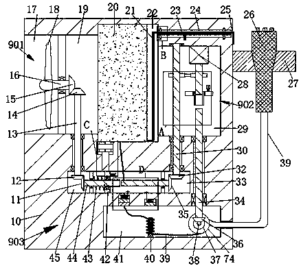
[0020] An automatically protected charging pile of the device of the present invention includes a casing 10 and a heat dissipation device 901 located in the casing 10, the heat dissipation device 901 includes a heat conduction groove 19, and the left end wall of the heat conduction groove 19 is connected to a There is a heat dissipation groove 17 that runs through the left end surface of the housing 10 on the left side, and the right side of the heat conduction groove 19 is connected with a cooling groo...


PUM


Abstract

The invention discloses a charging pile capable of achieving automatic protection. The charging pile comprises a shell and a heat dissipation device body located in the shell. The heat dissipation device comprises a heat conduction groove, wherein the left end wall of the heat conduction groove is communicated with a heat dissipation groove of which the left side penetrates through the left end surface of the shell; the right side of the heat conduction groove is communicated with a cooling groove; a conversion device is arranged on the right side of the cooling tank; the device can start thefan to dissipate heat when detecting that the heat is too high; meanwhile, when the external temperature rises, the semiconductor is used, and the semiconductor conductivity is increased; when the external temperature is reduced, the characteristic that the semiconductor conductivity is reduced automatically switches the semiconductor, the automatic switching is achieved, the charging efficiency is guaranteed, and the cooling is conducted according to the physical effect of Peltier; meanwhile, the charging current can be detected, the load is prevented from being too large, and circuit protection is conducted.

Description

technical field [0001] The invention relates to the technical field of semiconductors, in particular to an automatically protected charging pile. Background technique [0002] If the charging pile is overheated, it is necessary to find a way to let it dissipate heat. Compared with other power sources, the heat dissipation of the charging pile system is much larger, and the requirements for the thermal design of the system are extremely strict. There are currently four commonly used cooling modes: natural cooling (mainly Relying on heat sink), forced air cooling, water cooling, air conditioning, due to the influence of volume, cost, reliability and other factors, most companies currently use forced air cooling for processing, so this will inevitably bring Dust, corrosive gas, moisture and other interference. Contents of the invention [0003] In view of the deficiencies of the above-mentioned technologies, the present invention proposes a charging pile capable of automatic...

Claims


Application Information

Patent Timeline
IPC IPC(8): H02J7/00H05K7/20
CPCH05K7/20918Y02E60/10
Inventor 不公告发明人
Owner DONGYANG PINGZHOU ELECTRIC VEHICLE TECH CO LTD
Why Eureka
Try Eureka