fuel cell unit
A fuel cell and gas diffusion layer technology, applied in electrical components, battery electrodes, circuits, etc., can solve the problems of low cushioning, many energy-consuming processes, and uneven absorption thickness
- Summary
- Abstract
- Description
- Claims
- Application Information
AI Technical Summary
Problems solved by technology
Method used
Image
Examples
Embodiment 1
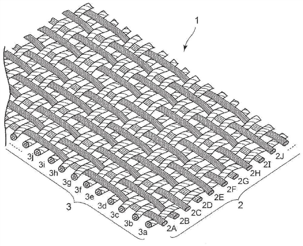
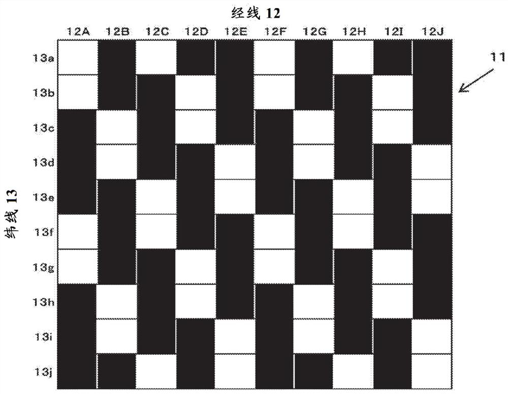
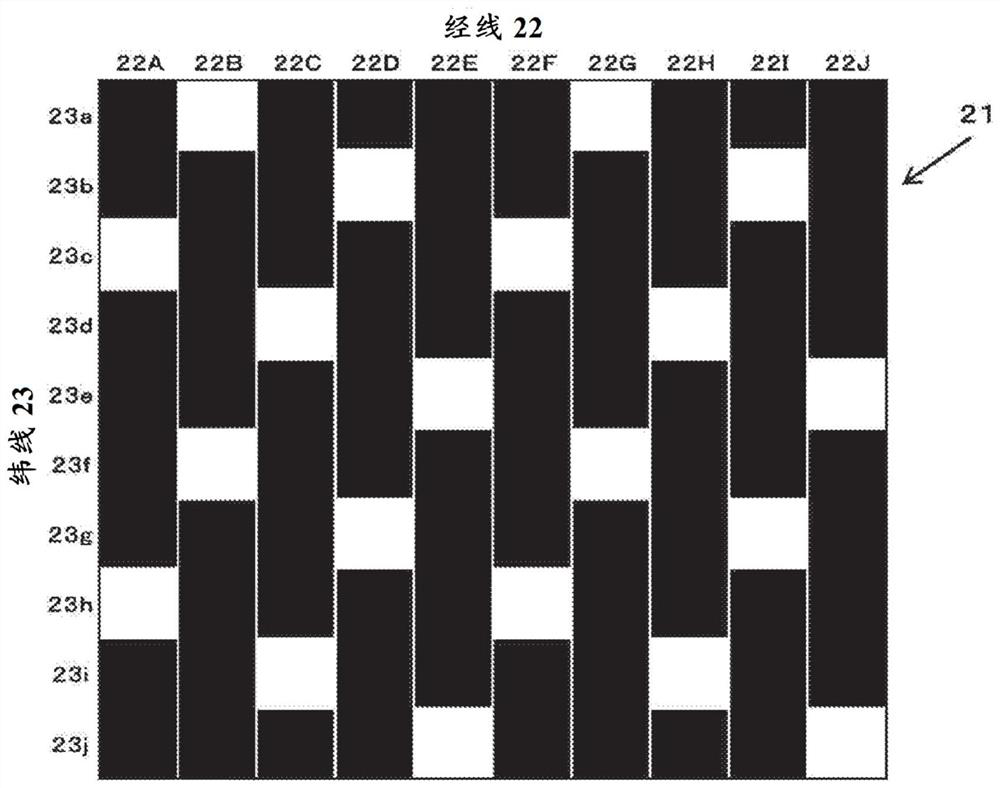
[0082] Using the GDL of each carbon fiber fabric using the material of the present invention and the comparative material, a fuel cell (hereinafter referred to as "cell") was produced, and the power generation performance of the cell was measured, and the measurement results will be described. The GDL used in this measurement was the GDL of each carbon fiber fabric using two types of the present invention materials (Inventive Materials 1 and 2) and two types of comparative materials (Comparative Materials 1 and 2). Inventive material 1 is figure 1 as well as figure 2 In the GDL of the twill weave shown (the weaving method in which one warp thread passes over three weft threads and then goes under two weft threads), only the warp threads are substantially untwisted threads. In addition, the material of the present invention 2 is the same as the material of the invention 1. figure 1 as well as figure 2 In the twill weave GDL shown, both the warp and weft are substantially u...
Embodiment 2
[0098] Next, in order to compare the ease of flowability of the fluid (water) in each GDL of the material of the present invention and the comparative material, a water flow test was performed. The GDLs used in this test were the present invention material 2 and the comparative material 2 (hereinafter referred to as the present invention material 3 and the comparative material 3) used in Example 1. Figure 12 A schematic plan view of the test apparatus used in this experiment is shown in Figure 13 shown in Figure 12 of the X-X section.
[0099] For this test setup, if Figure 12 as well as Figure 13 As shown in the figure, a GDL with a thickness of 0.1 mm × width 50 mm × length 100 mm is placed on a steel base, and a spacer is placed around the GDL, and the GDL is pressed from above with a transparent resin flat plate and a steel pressing plate. airtight. With regard to a closed GDL, it can be achieved by e.g. Figure 13 The pressure plate with the central opening and t...
Embodiment 3
[0102] Since the difference in the amount of bending under predetermined pressing was measured using the inventive material and the comparative material, the measurement results will be described. In addition, since the same invention material and comparative material were also used for the measurement of the electric power generation performance similar to Example 1, the measurement result is also demonstrated together.
[0103] The GDL used in the measurement of the amount of bending of the GDL in this example and the measurement of the power generation performance is a material obtained by curing both surfaces of the material of the present invention 1 used in Example 1 as the material of the invention (hereinafter referred to as the present invention). Material 4) and a material obtained by curing both surfaces of Comparative Material 1 used in Example 1 with a thermosetting resin (hereinafter referred to as Comparative Material 4) as a comparative material.
[0104] Regar...
PUM
| Property | Measurement | Unit |
|---|---|---|
| thickness | aaaaa | aaaaa |
Abstract
Description
Claims
Application Information
 - R&D
- Intellectual Property
- Life Sciences
- Materials
- Tech Scout
- Unparalleled Data Quality
- Higher Quality Content
- 60% Fewer Hallucinations
Browse by: Latest US Patents, China's latest patents, Technical Efficacy Thesaurus, Application Domain, Technology Topic, Popular Technical Reports.
© 2025 PatSnap. All rights reserved.Legal|Privacy policy|Modern Slavery Act Transparency Statement|Sitemap|About US| Contact US: help@patsnap.com


