Field crop canopy density detection method based on laser radar sensor

A lidar, field crop technology, applied in the direction of instruments, measuring devices, electromagnetic wave re-radiation, etc., can solve the problems of the detection system being large in size, difficult to implement, unable to reflect the density of the field canopy, etc. Unaffected by light, the effect of efficient spraying operations

Pending Publication Date: 2020-06-16
JIANGSU UNIV
View PDF5 Cites 5 Cited by
  • Summary
  • Abstract
  • Description
  • Claims
  • Application Information

AI Technical Summary

Problems solved by technology

[0003] Chinese patent (CN104457626A) uses the two-dimensional point cloud data generated by the ground laser radar measurement system, combined with computer graphics technology, to stitch the point cloud of each frame into a three-dimensional point cloud image, and obtain the leaf area index calculation from the point cloud image The relevant parameters are obtained from the mathematical model, and the leaf area index is obtained by inversion; this method needs to image the point cloud data, and the multi-frame two-dimensional point cloud stitching process and the subsequent point cloud processing process are more complicated, and the obtained leaf area index does not reflect the Density of the canopy in the field, no in-depth leaf distribution information on the upper, middle and lower parts of the canopy
Chinese patent (CN109006749A) installs multi-dimensional force sensors on the branch to detect random branch resistance information in the field, and establishes field canopy based on branch resistance through manual measurement of field canopy density information and comparative modeling between the two. Layer density detection model; this method only reflects the density of the canopy by detecting the branch resistance side of the canopy, and it is also unable to measure the distribution of leaves in the upper, middle, and lower parts of the plant canopy, and the detection system is too large to be easy. implement

Method used


Image

  • Field crop canopy density detection method based on laser radar sensor
  • Field crop canopy density detection method based on laser radar sensor
  • Field crop canopy density detection method based on laser radar sensor

Examples


Embodiment Construction

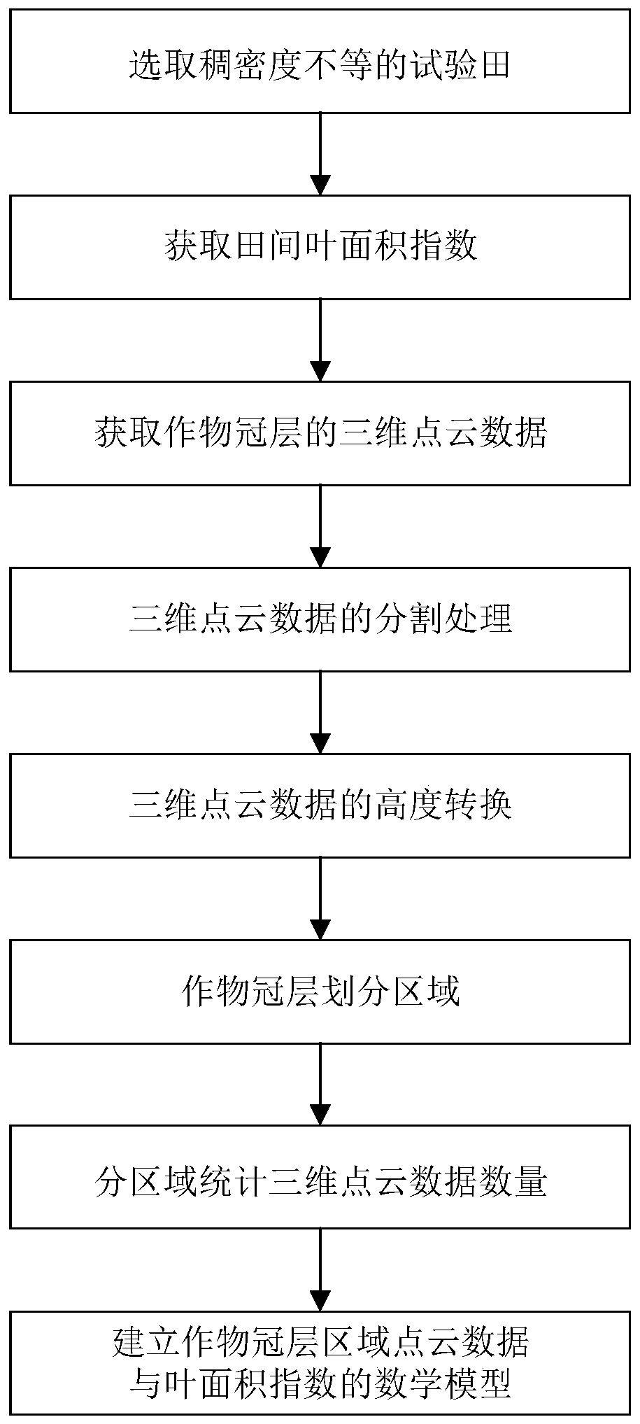
[0023] In order to further understand and understand the structural features and achieved effects of the present invention, preferred embodiments and accompanying drawings are used for detailed descriptions, which are described as follows.

[0024] Such as figure 1 Shown, a kind of field crop canopy density measuring method based on lidar sensor of the present invention (field crop in the present embodiment selects cotton), comprises the following steps:

[0025] Step (1), in the middle and late stages of cotton growth, select 5 fields that are sparse, relatively sparse, medium, relatively dense, and dense; The rectangular crop range (b is greater than 3a); within the rectangular range, randomly select 3 square areas with the width as the side length, and calculate the leaf area index.

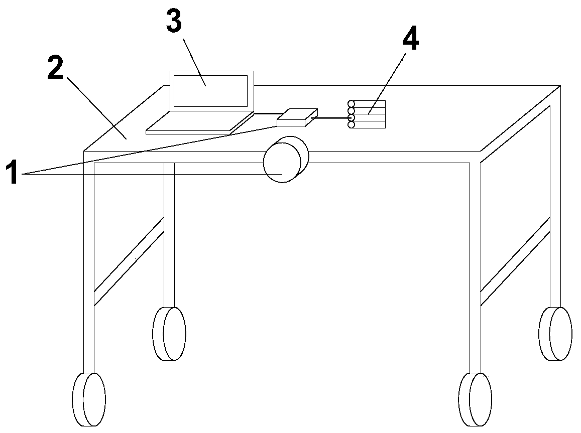
[0026] Step (2), build the detection device

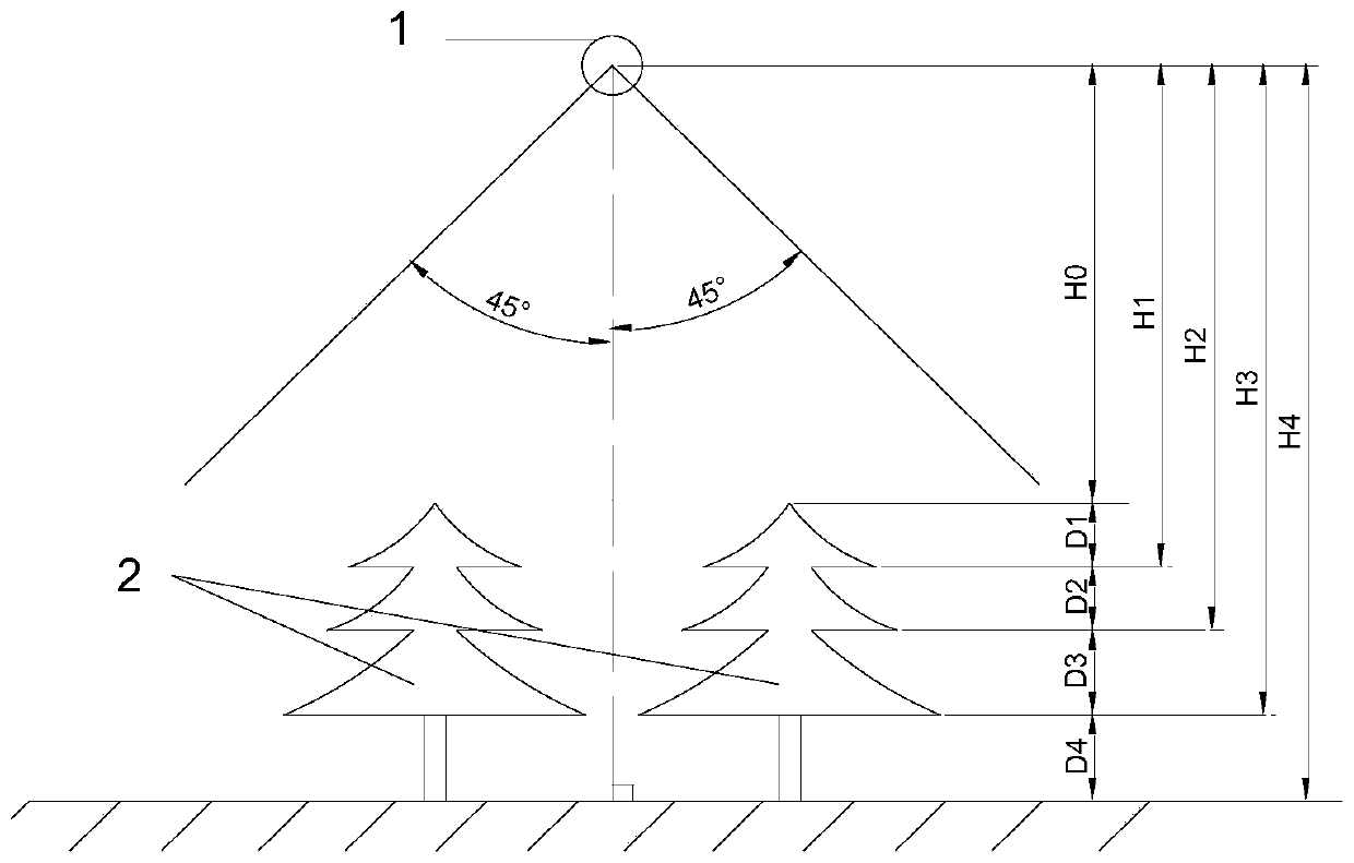
[0027] Such as figure 2 As shown, the laser radar sensor 1 is vertically installed and fixed at the center of the edge of the field walking fr...


PUM


Abstract

The invention discloses a field crop canopy density detection method based on a laser radar sensor. The method the method comprises the steps: selecting a crop field with an obvious canopy density difference, building a canopy density detection device, and acquiring three-dimensional point cloud data of the crop; carrying out segmentation removal, height conversion and crop canopy region divisionon the obtained original three-dimensional point cloud data; collecting leaf area data, calculating a leaf area index LAI of each field parcel, and acquiring a mathematical model of the crop canopy area point cloud number and the canopy density degree according to the crop leaf area indexes LAI of different density degrees and the crop canopy area point cloud number. The method is not influenced by illumination, the measurement speed is high, and subsequent pesticide application operation can be carried out more efficiently.

Description

technical field [0001] The invention belongs to the field of field information detection, and in particular relates to a field crop canopy density detection method based on a laser radar sensor. Background technique [0002] The leaf area index is the ratio of the total leaf area of ​​all plants and crops on a piece of land to the total land area, and it is related to the density, structure (single layer or multilayer) of vegetation, biological characteristics of trees (branch angle, leaf growth, etc.) Angle, shade tolerance, etc.) are related to environmental conditions (light, water, soil nutrition), and are a comprehensive indicator of the light energy utilization status of vegetation and canopy structure. Leaf area index is an important indicator of canopy density. Canopy density not only directly reflects the growth status of plants, but also describes the growth degree of plant canopy, and can reflect the upper, middle and lower canopy in the canopy. The accurate dete...

Claims


Application Information

Patent Timeline
Patent Type & Authority Applications(China)
IPC IPC(8): G01S17/89G06T7/10G06T7/62
CPCG01S17/89G06T7/10G06T7/62G06T2207/10028
Inventor 魏新华储宇豪王爱臣
Owner JIANGSU UNIV
Why Eureka
Try Eureka