
Control method of electric toothbrush

An electric toothbrush and control method technology, applied in the direction of program control, computer control, general control system, etc., can solve the problems that consumers cannot adapt, the elderly and children find it difficult to use electric toothbrushes, and cannot realize manual toothbrush ready-to-use, etc. Achieve the effect of improving user experience and protecting dental health

Active Publication Date: 2020-06-19
广州舒客实业有限公司
View PDF9 Cites 12 Cited by
  • Summary
  • Abstract
  • Description
  • Claims
  • Application Information

AI Technical Summary

Problems solved by technology

With the continuous advancement of science and technology in recent years, the functions and modes of electric toothbrushes have gradually increased. Compared with traditional manual toothbrushes, electric toothbrushes at this stage, whether it is a physical button or a touch button, need to press or touch the button to realize the electric toothbrush. The function of start-up and mode switching cannot achieve the effect of traditional manual toothbrushes out of the box, resulting in a large number of consumers unable to adapt to the change in the use method of transitioning from traditional manual toothbrushes to electric toothbrushes, especially today's electric toothbrushes Due to the continuous increase of functions and modes of toothbrushes, it is necessary to switch the functions and modes of electric toothbrushes by pressing the buttons of the electric toothbrush and matching different pressing methods and pressing times, which is too complicated and cumbersome for the elderly and children , making it difficult for the elderly and children to use an electric toothbrush to brush their teeth independently

Method used


Image

  • Control method of electric toothbrush
  • Control method of electric toothbrush
  • Control method of electric toothbrush

Examples


Embodiment 1

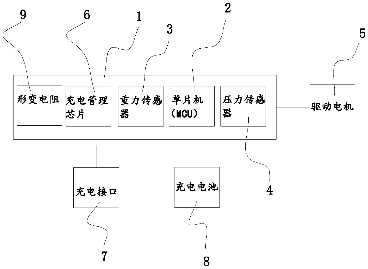
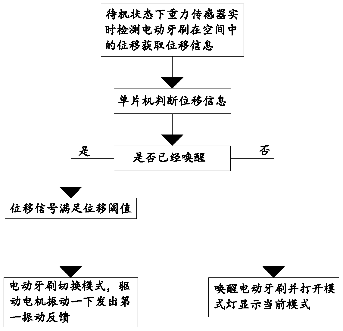
[0070] Embodiment one: if figure 2 As shown, when the electric toothbrush is in the standby state, the gravity sensor 3 of the present invention detects and acquires the displacement signal in real time, and sends it to the single-chip microcomputer 2, and the single-chip microcomputer 2 controls the electric toothbrush to enter the wake-up state, and turns on the mode light to display the position of the electric toothbrush. Current mode; after entering the wake-up state, the gravity sensor 3 continues to detect the displacement information of the electric toothbrush in real time and sends a displacement signal to the single-chip microcomputer 2. When the displacement signal received by the single-chip microcomputer 2 satisfies the set displacement threshold, the single-chip microcomputer 2. Control the electric toothbrush to switch modes, and control the drive motor 5 to send the first vibration feedback, and turn on the mode light to display the current mode.

Embodiment 2

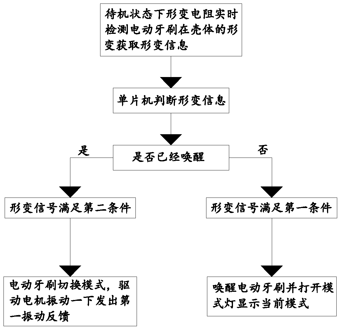
[0071] Embodiment two: if image 3 As shown, the deformation resistor 9 of the present invention detects and acquires the deformation signal in real time when the electric toothbrush is in a standby state, and sends it to the single-chip microcomputer 2. When the deformation signal received by the single-chip microcomputer 2 satisfies the first condition set, the The single-chip microcomputer 2 controls the electric toothbrush to enter the wake-up state, and turns on the mode light to display the current mode; after entering the wake-up state, the deformation resistor 9 detects the deformation information on the electric toothbrush housing in real time and converts it into a deformation signal and sends it to the single-chip microcomputer 2. 2. When it is judged that the deformation signal satisfies the set second condition, control the electric toothbrush to switch modes, and control the drive motor 5 to send the first vibration feedback, and turn on the mode light to display ...

Embodiment 3

[0074] Embodiment 3: The gravity sensor 3 of the present invention detects and obtains the displacement signal in real time when the electric toothbrush is in the standby state, and sends it to the single-chip microcomputer 2. When the single-chip microcomputer 2 receives the displacement signal and meets the displacement threshold, it controls the electric toothbrush Enter the wake-up state, and turn on the mode light to display the current mode of the electric toothbrush; after the electric toothbrush enters the wake-up state, the gravity sensor 3 detects the displacement information of the electric toothbrush immediately, and sends the displacement signal to the single-chip microcomputer 2, and the single-chip microcomputer 2 immediately Judging whether the displacement signal meets the set displacement threshold, if the displacement signal satisfies the displacement threshold, the single-chip microcomputer 2 controls the electric toothbrush to switch modes immediately after ...


PUM


Abstract

The invention discloses a control method of an electric toothbrush. The electric toothbrush comprises a pressure sensor, a deformation resistor and a control board. The control method comprises the following steps that the electric toothbrush is controlled by the control board to enter an awakening state; after the electric toothbrush enters the awakening state, when the deformation produced by ahousing of the electric toothbrush is detected by the deformation resistor, a deformation signal is transmitted, and the electric toothbrush is controlled by the control board to switch modes; when pressure information stressed on a toothbrush head is detected by the pressure sensor, a pressure signal is transmitted, a driving motor in the electric toothbrush is controlled by the control board tobe started, and the electric toothbrush enters a tooth brushing state; and after the tooth brushing state is entered, if the situation that the pressure information stressed by the toothbrush head isan initial pressure value is detected by the pressure sensor, the driving motor is controlled by the control board to be switched off, and the electric toothbrush enters the awakening state. Through the adoption of the control method disclosed by the invention, functions of non-key automatic awakening, automatic starting and automatic mode switching of the electric toothbrush can be realized.

Description

technical field [0001] The invention relates to the technical field of electric toothbrushes, in particular to an electric toothbrush control method. Background technique [0002] An electric toothbrush is a cleaning device that uses a high-speed vibrating motor to drive the brush head to rotate or vibrate to achieve the effect of cleaning teeth. Through the high-frequency vibration or rotation of the brush head, the toothpaste is instantly decomposed into fine foam, which penetrates deep into the gap between the teeth to clean the gap between the teeth, and the vibration of the bristles promotes blood circulation in the oral cavity, which has an unexpected massage effect on the gum tissue. Compared with traditional toothbrushes, electric toothbrushes can more thoroughly remove dental plaque and reduce oral diseases such as gingivitis, periodontal disease and gum bleeding, and are increasingly favored by consumers. [0003] Most of the current electric toothbrushes complete...

Claims


Application Information

Patent Timeline
Patent Type & Authority Applications(China)
IPC IPC(8): A61C17/26A61C17/34G01D21/02G05B19/042
CPCA61C17/221A61C17/26A61C17/34G01D21/02G05B19/042
Inventor 陈敏珊郭永辉祝智胜黄永胜谭建文
Owner 广州舒客实业有限公司
Learn More