Automatic liquid changing device for computer numerical control machine tool

A CNC machine tool, automatic technology, applied in the direction of metal processing machinery parts, maintenance and safety accessories, metal processing equipment, etc., can solve the problems of increasing the labor intensity of CNC machine tool personnel, affecting the normal use of CNC machine tools, and leakage of coolant, etc., to achieve structural Simple and reasonable, strong practicability, and the effect of avoiding vibration

Active Publication Date: 2020-06-19
山东卓益数控设备有限公司
View PDF13 Cites 2 Cited by
  • Summary
  • Abstract
  • Description
  • Claims
  • Application Information

AI Technical Summary

Problems solved by technology

After calculation and processing, various control signals are sent by the numerical control device to control the movement of the machine tool, and automatically process the parts according to the shape and size required by the drawing. Using coolant, after a period of use, the impurity content of the coolant will increase and its quality will decrease. It is necessary to replace the coolant of the machine tool at regular intervals. However, the existing manual replacement is required, which requires a large amount of operation and increases the number of CNC machine tool personnel. labor intensity, and takes a long time, which affects the normal use of the CNC machine tool, and it is easy to cause leakage of the coolant during the liquid change process, and the practicability is poor. Therefore, the present invention provides an automatic liquid change device for the CNC machine tool to solve the above problems.

Method used


Image

  • Automatic liquid changing device for computer numerical control machine tool
  • Automatic liquid changing device for computer numerical control machine tool
  • Automatic liquid changing device for computer numerical control machine tool

Examples


Embodiment Construction

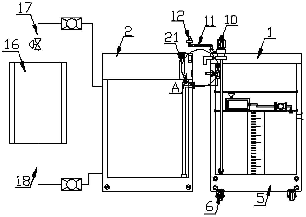
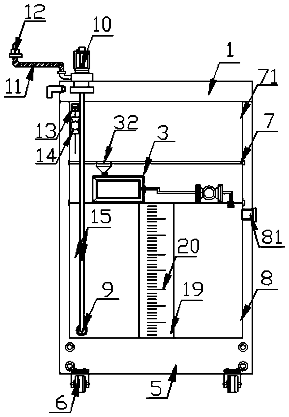
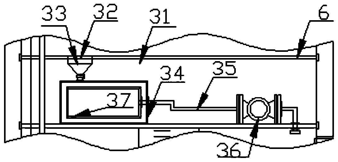
[0022] Such as Figure 1-6 As shown, this specific embodiment adopts the following technical solutions: an automatic liquid exchange device for numerical control machine tools, including a liquid exchange box 1, a circulation mechanism 3 and an installation protection mechanism 4, and the bottom of the liquid exchange box 1 is fixedly installed with Base 5, four moving wheels 6 are fixedly installed on the bottom of the base 5, and a protective mechanism 4 is installed on one side of the liquid exchange box 1, and the liquid exchange box 1 is connected with the machine tool box by the protective mechanism 4 The body 2 is detachably and fixedly installed, and the machine tool box 2 is fixedly installed on the bottom of the CNC machine tool 16, and the top of one side of the machine tool box 2 communicates with the input end of the cooling system of the CNC machine tool 16 through the liquid inlet pipe 17, so that The output end of the cooling system of the numerical control mac...


PUM


Abstract

The invention discloses an automatic liquid changing device for a computer numerical control machine tool. The automatic liquid changing device for the computer numerical control machine tool comprises a liquid changing box body, a circulating mechanism and an installation protection mechanism, wherein a base is fixedly installed at the bottom of the liquid changing box body, four moving wheels are fixedly installed at the bottom of the base, and the installation protection mechanism is installed on one side of the liquid changing box body; the liquid changing box and a machine tool box are detachably and fixedly installed through the installation protection mechanism, the machine tool box is fixedly installed at the bottom of the computer numerical control machine tool, the top of one side of the machine tool box communicates with the input end of a computer numerical control machine tool cooling system through a liquid inlet pipe, and the output end of the computer numerical controlmachine tool cooling system communicates with the bottom of one side of the machine tool box through a liquid return pipe; and water pumps are arranged on the liquid inlet pipe and the liquid return pipe. The automatic liquid changing device is simple and reasonable in structure, automatic liquid changing is achieved, operation difficulty is reduced, the liquid changing time is shortened, liquid changing energy consumption and cost are low, and moving flexibility of the liquid changing device is improved; and meanwhile, stability during liquid changing is guaranteed through the installation protection mechanism, so that liquid changing leakage is avoided.

Description

Technical field: [0001] The invention belongs to the technical field of cooling of numerically controlled machine tools, and in particular relates to an automatic liquid changing device for numerically controlled machine tools. Background technique: [0002] A CNC machine tool is an automatic machine tool equipped with a program control system, which can logically process the program specified by the control code or other symbolic instructions, decode it, express it in coded numbers, and input it into the CNC machine tool through the information carrier. device. After calculation and processing, various control signals are sent by the numerical control device to control the movement of the machine tool, and automatically process the parts according to the shape and size required by the drawing. Using coolant, after a period of use, the impurity content of the coolant will increase and its quality will decrease. It is necessary to replace the coolant of the machine tool at r...

Claims


Application Information

Patent Timeline
Patent Type & Authority Applications(China)
IPC IPC(8): B23Q11/10
CPCB23Q11/1069
Inventor 夏成雷夏荣海
Owner 山东卓益数控设备有限公司
Why Eureka
Try Eureka