Method and system for engine idle speed control

A technology of engine idle speed and engine speed, which is applied in the direction of engine control, machine/engine, and arrangement of multiple different prime movers of general power plants, etc. It can solve the problems of not allowing engine idle speed, unexpected vehicle movement, acceleration, etc. , to achieve the effect of improving vehicle fuel economy

Pending Publication Date: 2020-06-19
FORD GLOBAL TECH LLC
View PDF1 Cites 0 Cited by
  • Summary
  • Abstract
  • Description
  • Claims
  • Application Information

AI Technical Summary

Problems solved by technology

Specifically, even if the engine idle speed is reduced based on a more accurate estimate of the accessory load, the controller may n

Method used


Image

  • Method and system for engine idle speed control
  • Method and system for engine idle speed control
  • Method and system for engine idle speed control

Examples


Embodiment Construction

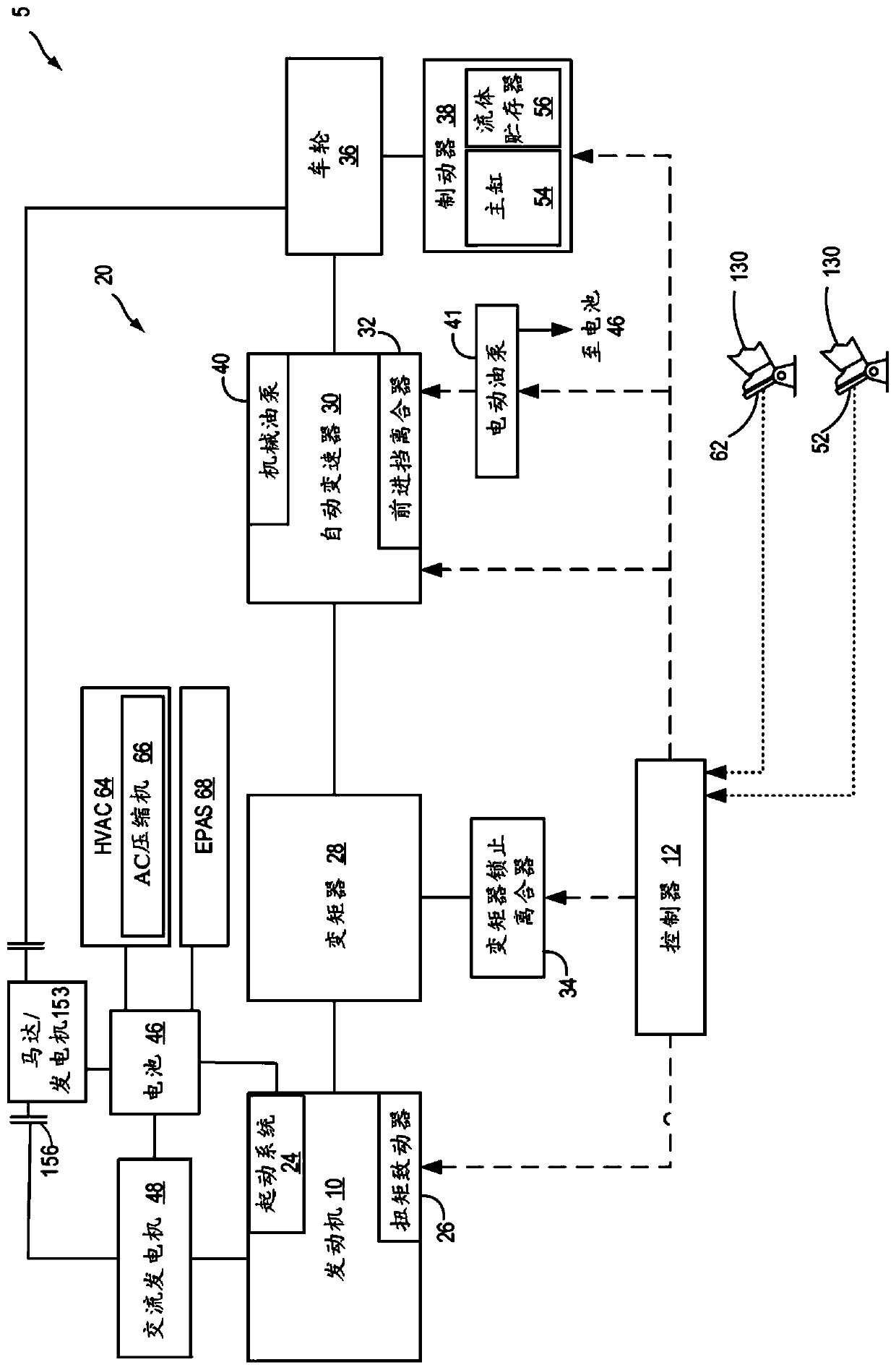
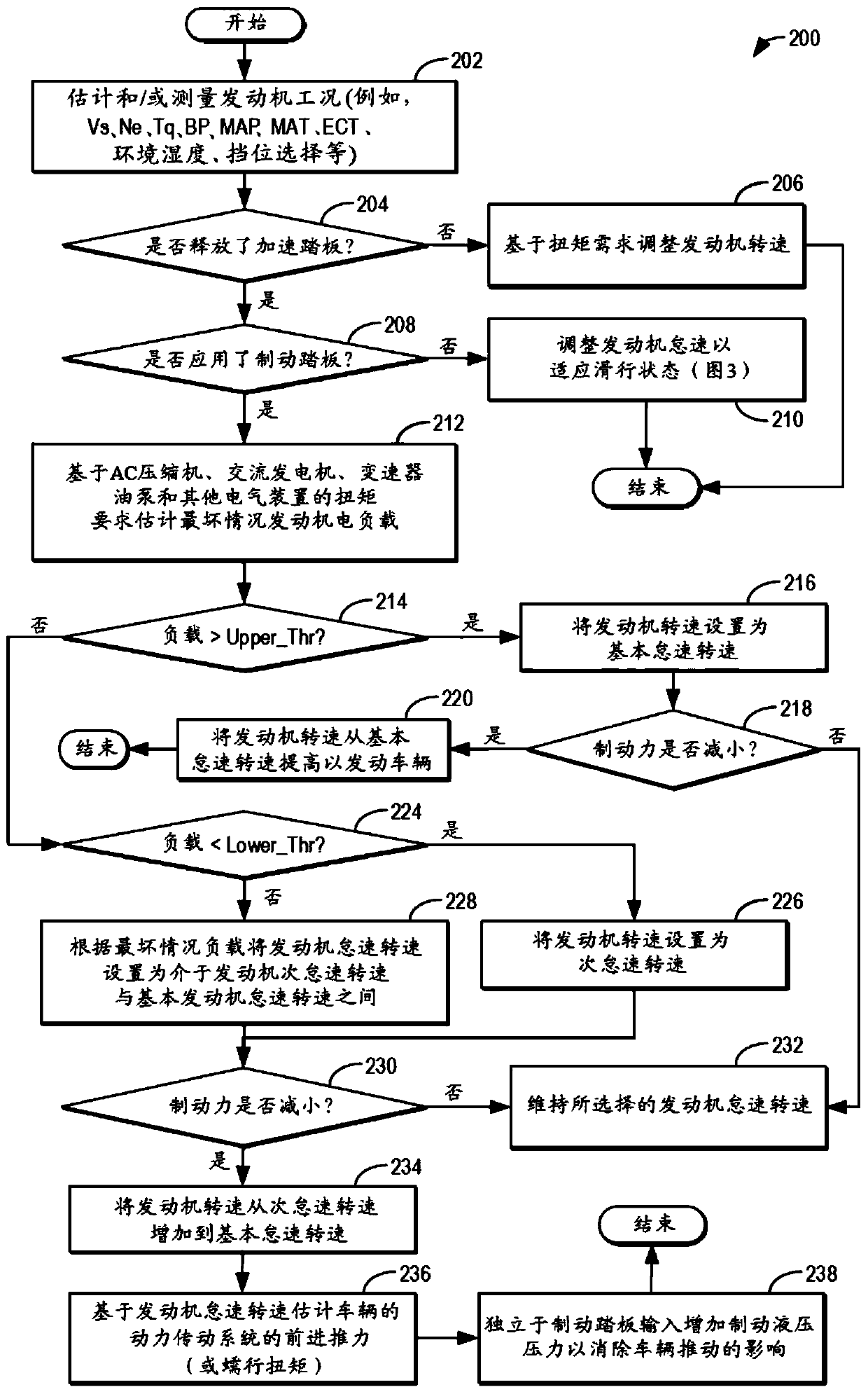
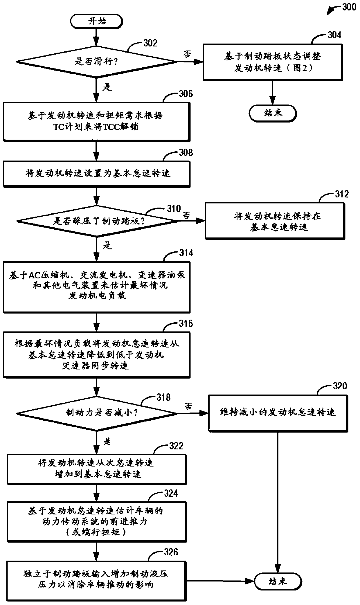
[0014] The following description relates to methods for improving vehicle systems such as figure 1 A system and method for fuel economy in a system). The engine controller can execute control routines such as figure 2 example routine) to reduce the engine idle speed below the base idle speed with the accelerator pedal released and the brake pedal applied. The idle speed may be reduced below a base idle speed based on an actual or predicted electrical load on the engine. After the brake pedal is released, the idle speed can be increased to the base speed for rapid vehicle acceleration. Simultaneously, hydraulic brake pressure can be increased while brake pedal input is decreased to counteract creep torque due to the rapid rise in engine idle speed. Such as image 3 As shown, a similar approach for the idle control routine may be performed during vehicle coasting in conjunction with transmission engine synchronous speed. Figure 4 A predictive example of reducing engine id...


PUM


Abstract

The invention provides a method and a system for engine idle speed control. Methods and systems are provided for improving fuel economy by opportunistically lowering engine idle speed below a base idle speed when electrical loads are not present. A hydraulic brake pressure is increased when the idle speed is raised, in anticipation of vehicle propulsion. The brake pressure counteracts any creep torque and unintended vehicle acceleration resulting from the rising engine idle speed.

Description

technical field [0001] The present description generally relates to methods and systems for controlling vehicle engine idle speed to improve vehicle fuel economy. Background technique [0002] The vehicle control system may be configured for engine idle speed control (ISC). While low engine idle speeds are known to improve fuel economy, there may be a number of constraints on ISC that force the engine idle speed to be higher than a desired engine idle speed. These constraints may include those related to meeting emissions requirements and maintaining acceptable drivability while providing fuel economy. Engine idle speed control is greatly aided by the loads placed on the engine by various engine driven vehicle components such as the alternator, AC compressor, and automatic transmission oil pump. Specifically, the engine speed is set to a worst case minimum idle speed that can satisfy each of a worst case alternator load, a worst case transmission pump load, and a worst cas...

Claims


Application Information

Patent Timeline
IPC IPC(8): B60W30/18B60W10/06B60W10/18B60W10/30B60W20/00
CPCB60W10/06B60W10/18B60W10/30B60W20/00B60W30/18018B60W2510/0638B60W2510/0657B60W2510/0666B60W10/184B60W30/1886B60W2540/10B60W2540/12B60W2710/0644B60W2710/182B60W2710/305F02D29/02F02D31/001F02D41/021F02D41/083F02D2200/602B60H1/00B60K6/387B60K6/40B60K6/54B60W2710/065B60Y2200/92F02D11/02
Inventor 拉尔夫·坎宁安罗斯·戴卡斯特拉·普西福尔
Owner FORD GLOBAL TECH LLC
Why Eureka
Try Eureka