Vision logic control method used for stacking machine

A technology of logic control and stacker, which is applied in the field of visual logic control of stacker, can solve problems such as complex wiring of electronic components, waste of system resources, obstacles to complex systems, multi-machine system development, etc., to achieve the significance of widespread application, The effect of saving costs and simplifying the storage system

Active Publication Date: 2020-06-19
广东键宇货架有限公司
View PDF7 Cites 2 Cited by
  • Summary
  • Abstract
  • Description
  • Claims
  • Application Information

AI Technical Summary

Problems solved by technology

[0003] 1. A large number of electronic components and complex wiring bring difficulties to production and maintenance. One problem will paralyze the entire system and fall into a long inspection process, and the larger the warehouse, the more serious the problem
[0004] 2. The stacker moves according to the position set by the program, and the shelf structure must be strictly established at the specified position, and the action position is seriously decoupled from the actual working conditions.
In case of slight deformation of various factors during the use of the shelf, resulting in a difference between the action position of the stacker and the actual position of the shelf, it will cause serious accidents, especially the automatic warehouse of the heavy-duty stacker with a cargo weight of more than one ton;
[0005] 3. The waste of system resources hinders the development of complex systems, multi-machine systems, etc.

Method used


Image

  • Vision logic control method used for stacking machine
  • Vision logic control method used for stacking machine
  • Vision logic control method used for stacking machine

Examples


Embodiment Construction

[0034] For better understanding and implementation, the technical solutions in the embodiments of the present invention will be clearly and completely described below in conjunction with the drawings in the embodiments of the present invention.

[0035] Unless otherwise defined, all technical and scientific terms used herein have the same meaning as commonly understood by one of ordinary skill in the technical field of the invention. The terms used herein in the description of the present invention are for the purpose of describing specific embodiments only, and are not intended to limit the present invention.

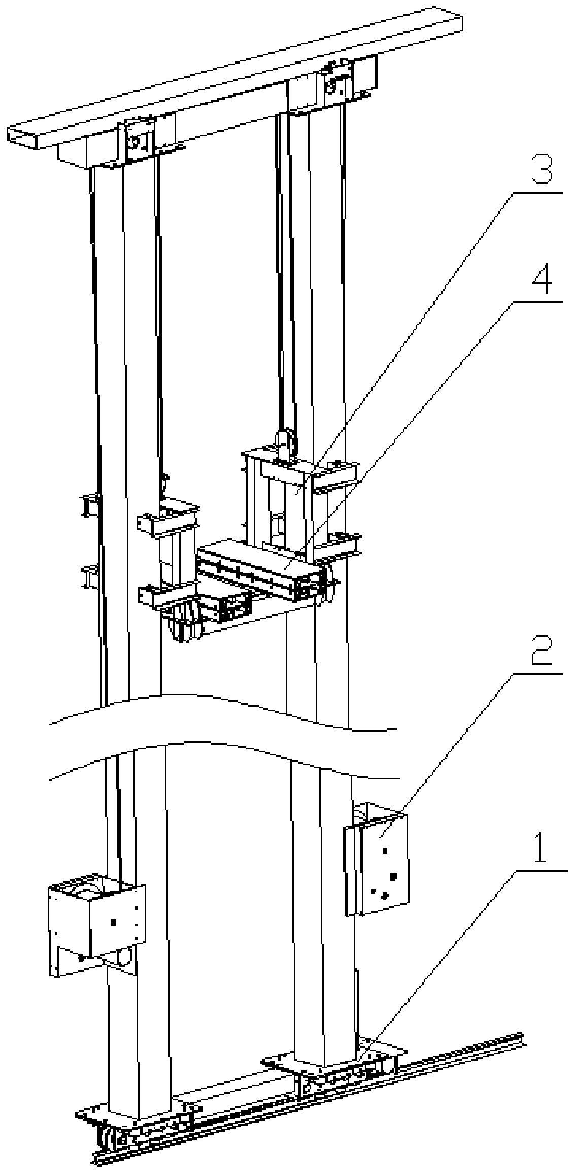
[0036] refer to figure 1 and figure 2 , the invention discloses a visual logic control method for a stacker, and the visual logic control method is generally applied to an automatic warehouse system with beam-type shelves. Wherein, the stacker includes a traveling mechanism 1, a lifting mechanism 2, a loading platform 3 and a cargo fork 4, the cargo fork 4 is instal...


PUM


Abstract

The invention discloses a vision logic control method used for a stacking machine. According to the vision logic control method, video on the movement route of the stacking machine is shot through a video recording device in real time, images are extracted, processed and analyzed through a microprocessor set to judge and accumulate the numbers of horizontal goods allocations and vertical goods allocations by which the stacking machine passes, and therefore judgement of the target goods allocation is completed, and fine adjustment is conducted on the position of the stacking machine in the later period to meet the requirement for taking and storing goods. According to the vision logic control method, the stacking machine is commanded to act according to the actual working condition, the safety problem caused by deviation of the goods shelf positions is solved, an automatic bin warehousing system is simplified, cost is saved, and wide application and popularization significance is achieved.

Description

technical field [0001] The invention relates to the field of stacking control of automatic warehouses, in particular to a visual logic control method for a stacker. Background technique [0002] In the currently visible automatic warehouses, the code disc method is used to control the stroke of each dimension of the stacker, and then a variety of components are used to limit the position, and then the cargo location is judged by means such as light indication and QR code reading. , these control methods have the following disadvantages: [0003] 1. A large number of electronic components and complex wiring bring difficulties to production and maintenance. One problem will paralyze the entire system and fall into a long inspection process, and the larger the warehouse, the more serious the problem. [0004] 2. The stacker moves according to the position set by the program, and the shelf structure must be strictly established at the designated position, and the action positio...

Claims


Application Information

Patent Timeline
Patent Type & Authority Applications(China)
IPC IPC(8): B65G1/04B65G1/137B65G57/00
CPCB65G1/04B65G1/1373B65G57/00
Inventor 简超贤徐如坤
Owner 广东键宇货架有限公司
Why Eureka
Try Eureka