
Combined one-way hinge for right-angle test piece loading test

A loading test, one-way technology, applied in the direction of applying stable tension/pressure to test the strength of materials, measuring devices, instruments, etc., can solve the problems of poor accuracy of test results, low possibility of reusability, and difficulty in fixing test pieces , to achieve the effect of reducing processing difficulty and cost, convenient processing and transportation, and saving test manpower and material resources

Active Publication Date: 2020-06-19
ZHEJIANG UNIV
View PDF12 Cites 0 Cited by
  • Summary
  • Abstract
  • Description
  • Claims
  • Application Information

AI Technical Summary

Problems solved by technology

However, the general laboratory load testing machine adopts the direct tension and direct compression method. The most important mechanical properties of right-angle members often lie in the limit of the bending moment at the corner. Taking the L-shaped structure as an example, if one limb is fixed and the other is stressed The loading method is prone to problems such as difficulty in fixing the specimen, complicated processing of auxiliary devices, and poor accuracy of test results.
[0004] The Chinese patent application document with the application number CN201910155625.8 proposes a one-way hinge member for seismic recovery of side walls, but the one-way hinge structure is still matched to the plane of the column bottom, and the non-separated one-way hinge structure is complicated to process High degree, less likely to be reused

Method used


Image

  • Combined one-way hinge for right-angle test piece loading test
  • Combined one-way hinge for right-angle test piece loading test
  • Combined one-way hinge for right-angle test piece loading test

Examples


Embodiment Construction

[0024] The technical solution in the present invention will be clearly and completely described below in conjunction with the accompanying drawings in the present invention. Obviously, the described embodiments are part of the embodiments of the present invention, not all of them. Based on the embodiments of the present invention, all other embodiments obtained by persons of ordinary skill in the art without making creative efforts shall fall within the protection scope of the present invention.

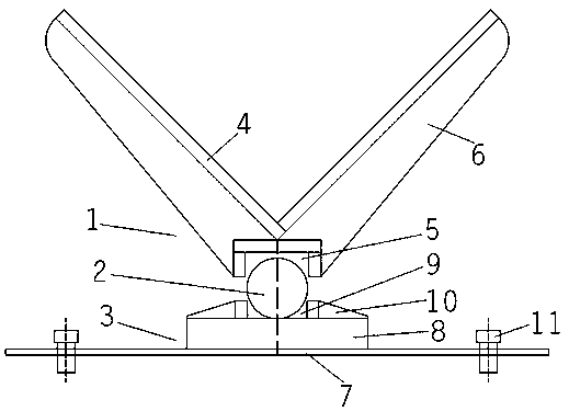
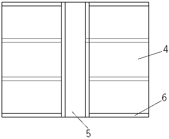
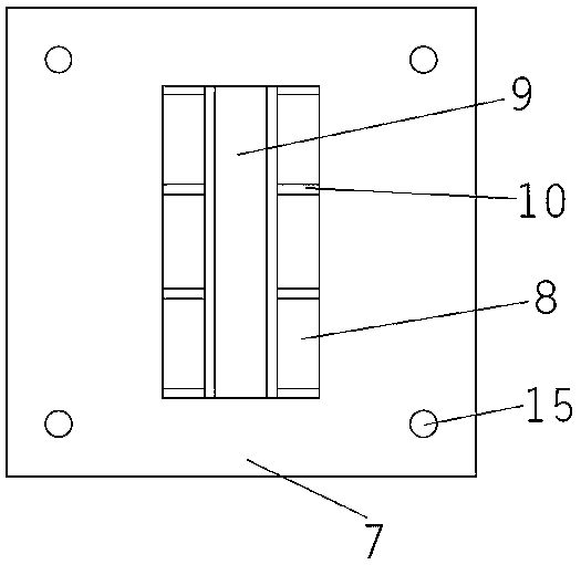
[0025] figure 1 It is the front view of the combined one-way hinge used for the loading test of the right-angle specimen in the preferred embodiment of the present invention, figure 2 It is the bottom view of the right angle wing assembly of the preferred embodiment of the present invention, image 3 It is a top view of the support seat assembly of the preferred embodiment of the present invention, as Figure 1-3 As shown, it includes a right-angle wing assembly 1, a roller shaft ...


PUM


Abstract

The invention relates to the technical field of reinforced concrete structure mechanical property testing, and in particular relates to a combined one-way hinge for a right-angle test piece loading test. The combined one-way hinge comprises a right-angle wing assembly, a roller shaft and a support seat assembly; the right-angle wing assembly comprises a right-angle plate, a first groove componentand a plurality of first reinforcing rib plates arranged between the right-angle plate and the first groove component; the opening of the right-angle plate and the opening of the first groove component are arranged back to back, and the right-angle plate and the first groove component are arranged in a centering mode; the support seat assembly comprises a base plate, a pier base, a second groove component and a plurality of second reinforcing rib plates arranged between the pier base and the second groove component; the opening of the first groove component and the opening of the second groovecomponent are oppositely arranged; and the roller shaft is arranged between the first groove component and the second groove component and abuts against the groove bottom of the first groove component and the groove bottom of the second groove component. The eccentric bending moment of the test piece restrained by the clamped support is eliminated through one-way hinge loading, and the test precision is greatly improved.

Description

technical field [0001] The invention relates to the technical field of mechanical performance testing of reinforced concrete structures, and more particularly, relates to a combined one-way hinge for loading tests of right-angle specimens. Background technique [0002] Reinforced concrete structures are widely used in above-ground and underground projects. In addition to the above-ground structures that are common in daily life, there are also urban lifeline projects such as underground box culverts, pipe galleries, and tunnels. Conventional reinforced concrete members are regular cuboid structures, such as beams, slabs and columns, etc., but in complex engineering environments and stress requirements, there are also a lot of special-shaped reinforced concrete members, such as T-shaped, L-shaped, square right-angled members, round Shaped semicircular components are commonly used component forms in engineering construction. Engineering construction consumes a lot of manpower...

Claims


Application Information

Patent Timeline
IPC IPC(8): G01N3/08G01N3/02
CPCG01N3/02G01N3/08G01N2203/0262
Inventor 王永俊王激扬潘海龙陈勇莫佳杰
Owner ZHEJIANG UNIV
Learn More