Method for calculating track mapping deformation after earthquake-induced damage of high-speed railway bridge

A technology of high-speed railways and calculation methods, applied in the direction of tracks, track maintenance, roads, etc., can solve problems such as increased wheel-rail interface disturbance, aggravated train vibration, and little research on the mapping relationship between deformations

Active Publication Date: 2020-06-19
CENT SOUTH UNIV
View PDF9 Cites 7 Cited by
  • Summary
  • Abstract
  • Description
  • Claims
  • Application Information

AI Technical Summary

Problems solved by technology

[0002] Under the earthquake, the bridge structure will inevitably produce various damage and deformation modes such as pier inclination, girder body misalignment and rotation angle, and support deformation. Most of these accumulated residual damage deformations will be mapped to the rail surface, causing additional track irregularities
When the train passes by at high speed, the additional irregularity of the track will increase the disturbance of the wheel-rail interface, and then cause the vibration of the train to increase through the dynamic interaction of the wheel and rail, resulting in the deterioration of the safety and comfort indicators of the train, and ultimately affecting the operation of the high-speed train. Safety
[0003] However, there is still little research on the mapping relationship between track irregularities on high-speed railway bridges and earthquake damage and deformation of sub-rail components, and it is difficult to determine the safe speed limit for high-speed railway bridges after earthquakes
[0004] The existing calculation methods for the mapping relationship between track irregularities and structural deformation are all based on structural micro-segment equilibrium conditions. Since the track structure is a multi-layer laminated beam structure, the calculation method is cumbersome and complicated.
Moreover, in the calculation method, the influence of contact nonlinearity between layers of the track structure is not considered, and the influence of the boundary conditions of the subgrade is not considered.

Method used


Image

  • Method for calculating track mapping deformation after earthquake-induced damage of high-speed railway bridge
  • Method for calculating track mapping deformation after earthquake-induced damage of high-speed railway bridge
  • Method for calculating track mapping deformation after earthquake-induced damage of high-speed railway bridge

Examples


Embodiment 1

[0103] 1. Basic assumptions

[0104] In order to establish the calculation model of the mapping relationship between the deformation of the bridge structure and the deformation of the ballastless track structure, the following basic assumptions are made:

[0105] 1.1 The mapping analytical model (Analytical model-1, referred to as "AM-1") when the contact between layers of the track structure is considered elastic:

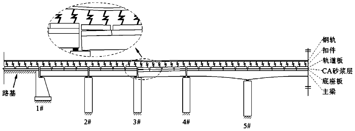
[0106] For the unit slab ballastless track, its structural diagram is as follows: figure 1 as shown,

[0107] (a) The track structure and main girder are simulated by composite beams, in which the track slab is regarded as a free beam at both ends without interconnection in the longitudinal bridge direction; since the base plate and the beam body are firmly connected by pre-embedded steel bars, it is assumed that the deformation of the two is coordinated ( For convenience, the two are collectively referred to as the main beam in the following text);

[0108] (b...

Embodiment 2

[0183] Calculation example: In order to verify the applicability and accuracy of the theoretical model, the unit slab ballastless track-continuous girder bridge system is taken as an example.

[0184] Based on the large-scale general finite element software ANSYS, the finite element model (Finite element model, referred to as "FEM") of the unit slab ballastless track-continuous girder bridge system was established. The spring in the subgrade section uses the Combine 14 unit, and the mortar layer uses the nonlinear spring unit Combine 40; the deformation of the bridge structure such as the bearing is simulated by imposing displacement constraints at the corresponding beam body bearing positions, and the simply supported boundary is used at the end of the rail beam. Eliminate the rail boundary effect of the subgrade section by taking enough calculation length of the subgrade section.

[0185] Table 1 Unit slab ballastless track-bridge system parameters

[0186]

[0187] Note...


PUM


Abstract

The invention discloses a method for calculating track mapping deformation after earthquake-induced damage of a high-speed railway bridge. The method comprises the following steps: S1, establishing abasic hypothesis; s2, establishing a mapping relation calculation model between bridge structure deformation and ballastless track structure deformation; s3 model solution. The invention provides a method for calculating a mapping relation between track irregularity on a high-speed railway bridge and earthquake damage deformation of parts below the track, which is suitable for various track structural forms in a high-speed railway. Quantitatively analyzing a mapping relation between accumulated damage of key components of a pier, a support and a track structure and track surface deformation inthe high-speed railway bridge; the method overcomes the defect that nonlinearity of interlayer contact of a track structure is not considered in an existing method for calculating the mapping relation between track irregularity on a high-speed railway bridge and seismic damage deformation of components under the track; the method overcomes the defect that roadbed boundary conditions are not considered in an existing method for calculating the mapping relation between the track irregularity on the high-speed railway bridge and the seismic damage deformation of the under-track part.

Description

technical field [0001] The invention relates to a calculation method for track mapping deformation after earthquake-induced damage of a high-speed railway bridge. Background technique [0002] Under the earthquake, the bridge structure will inevitably produce various damage and deformation modes such as pier inclination, girder body misalignment and rotation angle, and support deformation. Most of these accumulated residual damage deformations will be mapped to the rail surface, causing additional track irregularities. When the train passes by at high speed, the additional irregularity of the track will increase the disturbance of the wheel-rail interface, and then cause the vibration of the train to increase through the dynamic interaction of the wheel and rail, resulting in the deterioration of the safety and comfort indicators of the train, and ultimately affecting the operation of the high-speed train. Safety. [0003] However, there are few studies on the mapping relat...

Claims


Application Information

Patent Timeline
Patent Type & Authority Applications(China)
IPC IPC(8): G06F30/13G06F30/23G06F17/15G06F17/13G06F17/12E01B35/12G06F111/10
CPCG06F17/12G06F17/13G06F17/15E01B35/12Y02T90/00
Inventor 蒋丽忠聂磊鑫周旺保冯玉林郑兰刘丽丽刘韶辉吴凌旭许添鑫
Owner CENT SOUTH UNIV
Why Eureka
Try Eureka