Orthopedic brace for relieving O and X-shaped legs of knee joints
An orthopedic brace and knee joint technology, applied in the field of medical devices, can solve problems such as high technical requirements, large surgical trauma, and excessive bleeding, and achieve the effects of correcting knee joint valgus deformity, reducing load, and reducing relative displacement
- Summary
- Abstract
- Description
- Claims
- Application Information
AI Technical Summary
Problems solved by technology
Method used
Image

Examples
Embodiment 1
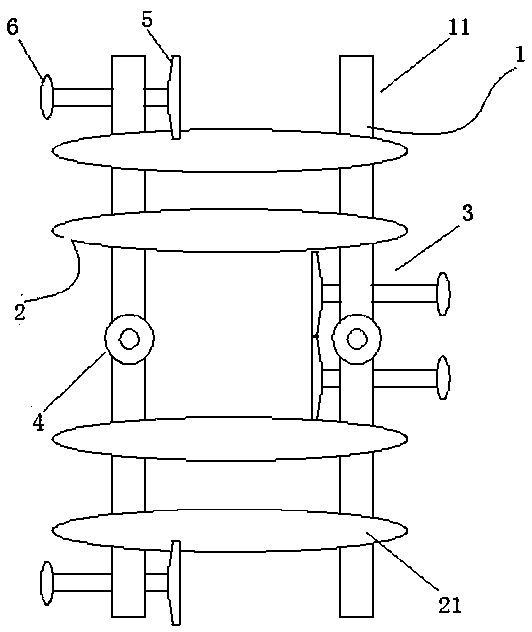
[0026] combined with Figure 1~2 , an orthopedic brace for improving the O-shaped and X-shaped legs of the knee joint, comprising a support body 1, a knee joint fixing belt 2 fixed on the outside of the support body 1, and a threaded fixing rod 3 movably threaded on the support body 1, It also includes a knee joint sheave 4 arranged on the support body 1, wherein,
[0027] The branch body 1 is located outside the knee joint and extends to the upper and lower ends respectively to the mid-thigh and the mid-calf;
[0028] The knee joint fixing belt 2 is divided into upper and lower groups, one group is set on the upper part of the support body 1 and is located in the middle of the thigh, and the other group is set on the lower part of the support body 1 and is located in the middle of the calf; the two ends of the knee joint fixing belt 2 are free state;
[0029] The threaded fixed rod 3 ends and the contact position with the thigh are provided with an arc-shaped inner support ...
Embodiment 2
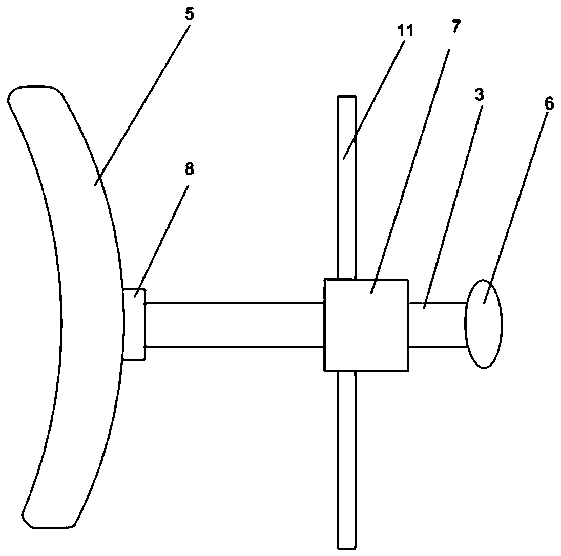
[0048] Other structures remain unchanged, and only the connection relationship between the threaded fixing rod 3 and the connecting rod 11 and the inner support 5 is changed, specifically: the threaded fixing rod 3 and the connecting rod 11 are provided with a nut-7; The connection between the rod 3 and the inner support 5 is provided with a nut 2 8, and the nut 2 8 is screwed on the outside of the threaded fixing rod 3 .
[0049] In terms of connection, the present application sets a nut 1 7 and a nut 2 8 that are screwed together on the threaded fixing rod 3, wherein the nut 2 8 is located at the position where the inner support 5 is affixed to each other, and the nut 1 7 is located on the threaded fixing rod. 3 and close to the other end, and a part of nut one 7 is embedded in the connecting rod 11.
PUM
 Abstract
Description
Claims
Application Information