Wireless charging coupling mechanism and unmanned aerial vehicle

A wireless charging and coupling mechanism technology, applied in charging stations, electric vehicle charging technology, motor vehicles, etc., can solve problems such as difficulty in directly adapting to the frame structure of drones, increasing flight resistance of drones, and affecting flight safety. Achieve the effect of light weight, good lateral offset characteristics and good symmetry

Active Publication Date: 2020-06-23
JIANGSU FRONTIER ELECTRIC TECH +1
View PDF5 Cites 7 Cited by
  • Summary
  • Abstract
  • Description
  • Claims
  • Application Information

AI Technical Summary

Problems solved by technology

[0004] In the prior art, in order to realize the wireless charging of UAVs, it is usually modified on the existing UAV frame structure. The commonly used wireless charging system mostly uses a single planar coil. In order to ensure its charging performance, the coil area is large and can be directly When used in various existing drone models, it is difficult to directly adapt to the existing rack structure of the drone, and it is easy to increase the flight resistance of the drone, which affects flight safety

Method used


Image

  • Wireless charging coupling mechanism and unmanned aerial vehicle
  • Wireless charging coupling mechanism and unmanned aerial vehicle
  • Wireless charging coupling mechanism and unmanned aerial vehicle

Examples


Embodiment Construction

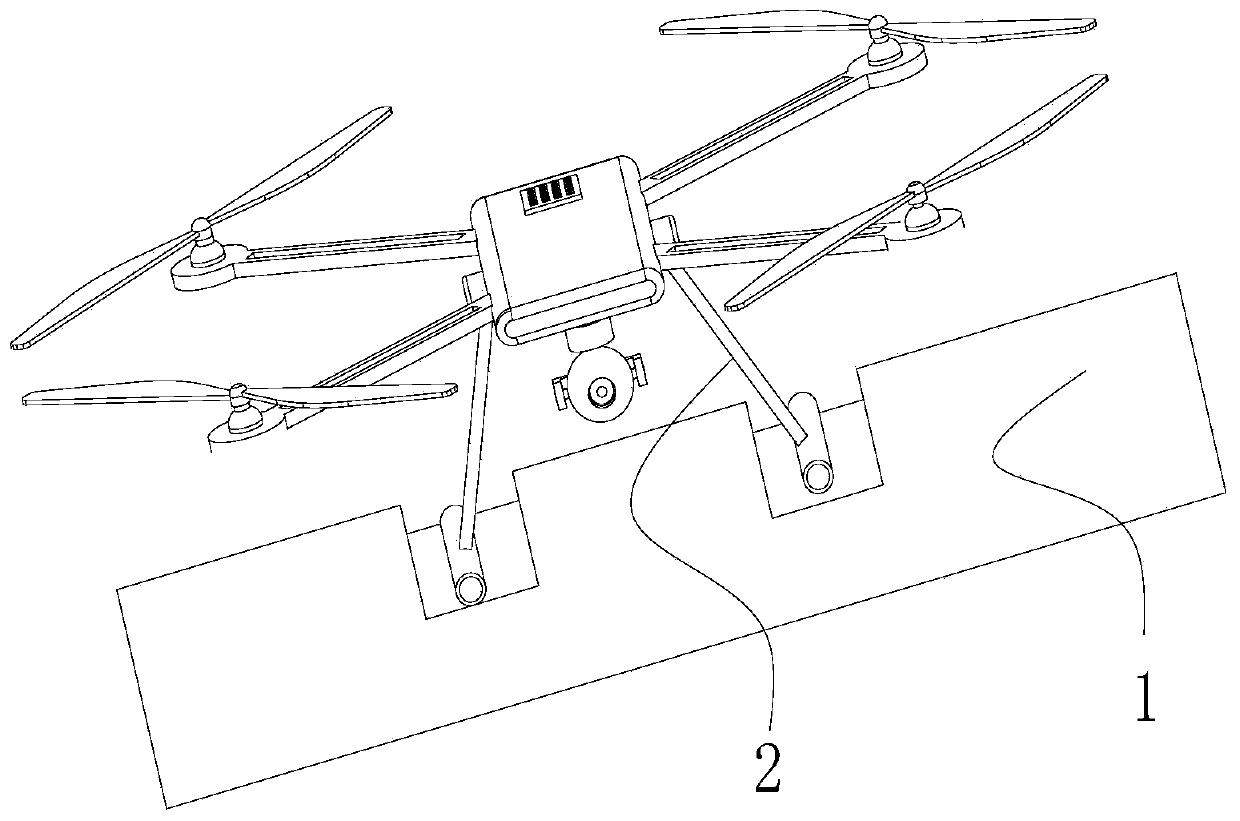
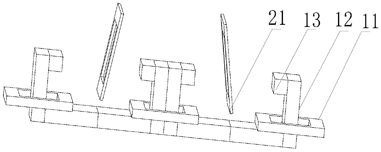
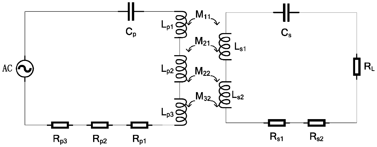
[0027] An embodiment of the present invention provides a wireless charging coupling mechanism, including a transmitting end and a receiving end, the transmitting end includes three serially connected transmitting coils and an E-shaped magnetic core, and the receiving end includes two serially connected The receiving coil, the E-shaped magnetic core is arranged horizontally, and the three transmitting coils are respectively wound on each column of the E-shaped magnetic core according to the planar ring; the two receiving coils at the receiving end are arranged according to a predetermined The offset angle is arranged sideways, and when the receiving end is close to the transmitting end, the two receiving coils are respectively embedded between two adjacent columns of the E-shaped magnetic core.

[0028] The mechanism adopts multi-segment distributed transmitting coils and receiving coils. On the premise of ensuring the efficiency of wireless charging, it can significantly reduce...


PUM


Abstract

The invention discloses a wireless charging coupling mechanism and an unmanned aerial vehicle. The coupling mechanism comprises a transmitting end and a receiving end; the transmitting end comprises an E-shaped magnetic core and three transmitting coils, wherein the three transmitting coils are connected in series; the receiving end comprises two receiving coils which are connected in series; theE-shaped magnetic core is horizontally arranged; the three transmitting coils are annularly wound on each stand column of the E-shaped magnetic core according to a plane; the two receiving coils of the receiving end are laterally arranged according to a preset deviation angle; and when the receiving end approaches the transmitting end, the two receiving coils are embedded spaces between the two adjacent stand columns of the E-shaped magnetic core respectively. The coils of the receiving end are free of a magnetic core and light in weight; the coupling mechanism is based on the horizontal footstool of the unmanned aerial vehicle, so that the structure of the unmanned aerial vehicle is not needed to be greatly modified; the coupling mechanism is easy to install and good in symmetry; the balance performance of the unmanned aerial vehicle will not be influenced; camera devices such as a cradle head of the unmanned aerial vehicle will not be shielded; and meanwhile, the coupling mechanismhas a better transverse offset characteristic.

Description

technical field [0001] The invention relates to a wireless charging coupling mechanism and an unmanned aerial vehicle, belonging to the technical field of wireless charging. Background technique [0002] In recent years, the UAV market is extremely hot. The short battery life is a common problem of UAVs. UAVs need to replace or recharge their batteries after 20-30 minutes of continuous flight. The ability of UAVs to perform tasks autonomously is seriously limited Capacity limitations. [0003] There are mainly three types of solutions for the battery life of UAVs. One is to equip UAVs with new energy power generation equipment such as solar cells, so that UAVs can automatically replenish power; The man-machine can carry more power at one time; the third is to develop an automatic charging technology that does not require manual assistance, so that the drone can realize power replenishment during the cruise and extend the cruise range. As one of the emerging charging techno...

Claims


Application Information

Patent Timeline
Patent Type & Authority Applications(China)
IPC IPC(8): B60L53/12B64F1/00H02J50/40
CPCB60L2200/10B64F1/00B60L53/12H02J50/40Y02T10/70Y02T10/7072Y02T90/14
Inventor 翟学锋王红星李军黄郑朱洁刘斌王智慧左志平
Owner JIANGSU FRONTIER ELECTRIC TECH
Why Eureka
Try Eureka