
Deformation control method in laser cladding of bimetal guide rail

A laser cladding and deformation control technology, applied in metal material coating process, coating and other directions, can solve problems such as warping deformation, achieve the effect of small deformation, reduce residual stress, and improve service life

Active Publication Date: 2022-03-11
XIAN RES INST OF CHINA COAL TECH& ENG GROUP CORP
View PDF0 Cites 0 Cited by
  • Summary
  • Abstract
  • Description
  • Claims
  • Application Information

AI Technical Summary

Problems solved by technology

[0005] The purpose of the present invention is to provide a method for controlling deformation in laser cladding of bimetallic guide rails, which can effectively overcome the defects of the prior art, can improve the problem of warpage and deformation in the process of cladding guide rails, reduce stress imbalance, and reduce warpage out of shape

Method used


Image

  • Deformation control method in laser cladding of bimetal guide rail
  • Deformation control method in laser cladding of bimetal guide rail
  • Deformation control method in laser cladding of bimetal guide rail

Examples


Embodiment Construction

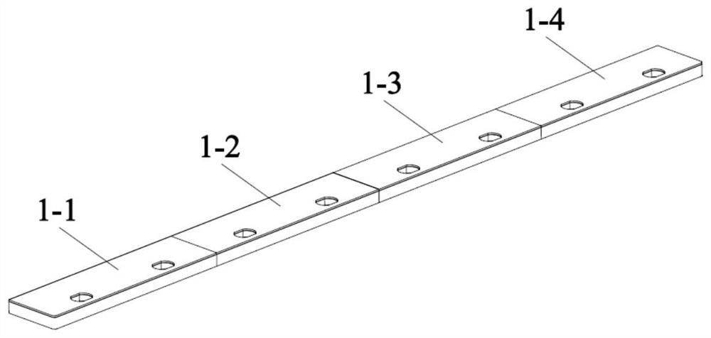
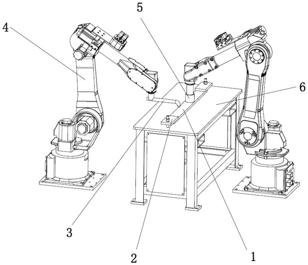
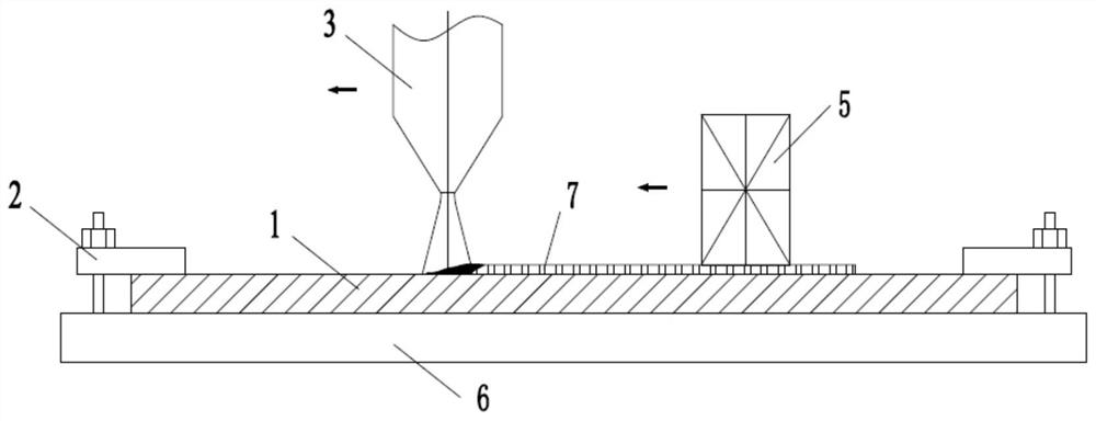
[0026] see Figure 1 to Figure 4 , shows the method for controlling deformation in laser cladding of bimetallic rails of the present invention.

[0027] The deformation control method in the laser cladding of the bimetal guide rail includes the following steps:

[0028] Step 1: Divide the long guide rail into multiple guide rail segments (the figure shows four guide rail segments of equal length, including the first guide rail segment 1-1, the second guide rail segment 1-2, the third guide rail segment 1-3 and The fourth guide rail section 1-4), in the specific setting, the shorter the length, the smaller the stress deformation during the cladding process, but the too short guide rail section will lead to complicated follow-up procedures and difficult to control during cladding, therefore, the appropriate The length limit is the guarantee for the smooth progress of the cladding process. In the present invention, the preferred length is 200mm-300mm;

[0029] Step 2: Fix the g...


PUM

PropertyMeasurementUnit
lengthaaaaaaaaaa

Abstract

A method for controlling deformation in laser cladding of a bimetal guide rail, which includes the following steps: Step 1: Divide a long guide rail into multiple guide rail segments; Step 2: Fix the guide rail base of any guide rail segment in the multiple guide rail segments to the bimetal Guide rail laser cladding system; Step 3: The mechanical arms of the two industrial robots respectively hold the laser cladding spray gun and the ultrasonic excitation device for cladding of the guide rail section, and the ultrasonic excitation device moves in the same direction as the laser cladding spray gun ; Step 4: after cladding the guide rail section, the guide rail section is processed and formed, and then the cladding process of each guide rail section is completed in turn, and finally each guide rail section is combined into a guide rail; thus, the technical solution of the present invention is compatible with existing Compared with the manufacturing process of grinding guide rail, the deformation of the manufactured bimetallic guide rail is extremely small. After the wear-resistant layer is clad, it does not need to be ground again because of the warping of the guide rail. Therefore, the thickness of the wear-resistant layer is uniform, the mechanical properties will not be damaged, and the maintenance cost is reduced. And the cost of use, greatly improving the service life of the guide rail.

Description

technical field [0001] The invention relates to the technical field of ultra-high-speed laser cladding of drilling machinery, in particular to a method for controlling deformation in laser cladding of bimetal guide rails. Background technique [0002] As one of the main components of the drilling rig, the guide rail is the benchmark and support point for the movement of the power head, and is a key component that affects the safe operation of the drilling rig. At present, the length of the wear-resistant guide rail manufactured by ultra-high-speed laser cladding technology is generally 600mm to 2000mm. Laser cladding metal wear-resistant layer directly on the 45# steel guide rail will cause slight warping deformation of the guide rail base. Reduce the thickness of the wear-resistant layer at the warped end. In the later use process, the guide rail will be scratched in the thin wear-resistant layer area, which will affect its normal use. [0003] In view of the above problem...

Claims


Application Information

Patent Timeline
Patent Type & Authority Patents(China)
IPC IPC(8): C23C24/10
CPCC23C24/103
Inventor 温国栋鄢忠方田东庄董萌萌蔺高峰路前海康奇岳范运林牟培英
Owner XIAN RES INST OF CHINA COAL TECH& ENG GROUP CORP
Learn More