
Enclosure device and soil remediation method

A technology of soil remediation and soil, which is applied in protection devices, sheet pile walls, buildings, etc., and can solve problems such as secondary pollution of soil

Pending Publication Date: 2020-06-23
SHANGHAI MECHANIZED CONSTR GRP
View PDF0 Cites 1 Cited by
  • Summary
  • Abstract
  • Description
  • Claims
  • Application Information

AI Technical Summary

Problems solved by technology

[0005] The purpose of the present invention is to provide an enclosure device and soil remediation method, which can solve the problem of secondary pollution when excavating the soil

Method used


Image

  • Enclosure device and soil remediation method
  • Enclosure device and soil remediation method
  • Enclosure device and soil remediation method

Examples


Embodiment 1

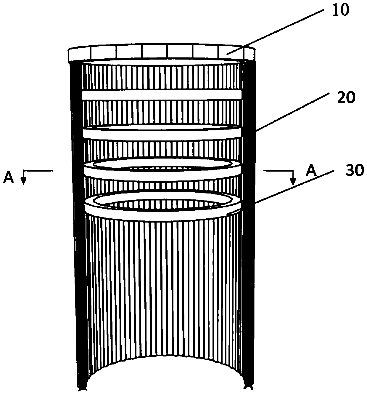
[0041] Such as figure 1 As shown, this embodiment provides an enclosure structure for soil enclosure, including:

[0042] The steel structure ring beam 10 is arranged in the soil and the upper surface is flush with the surface of the soil. The steel structure ring beam 10 includes two circular steel members, and the two steel members are arranged concentrically;

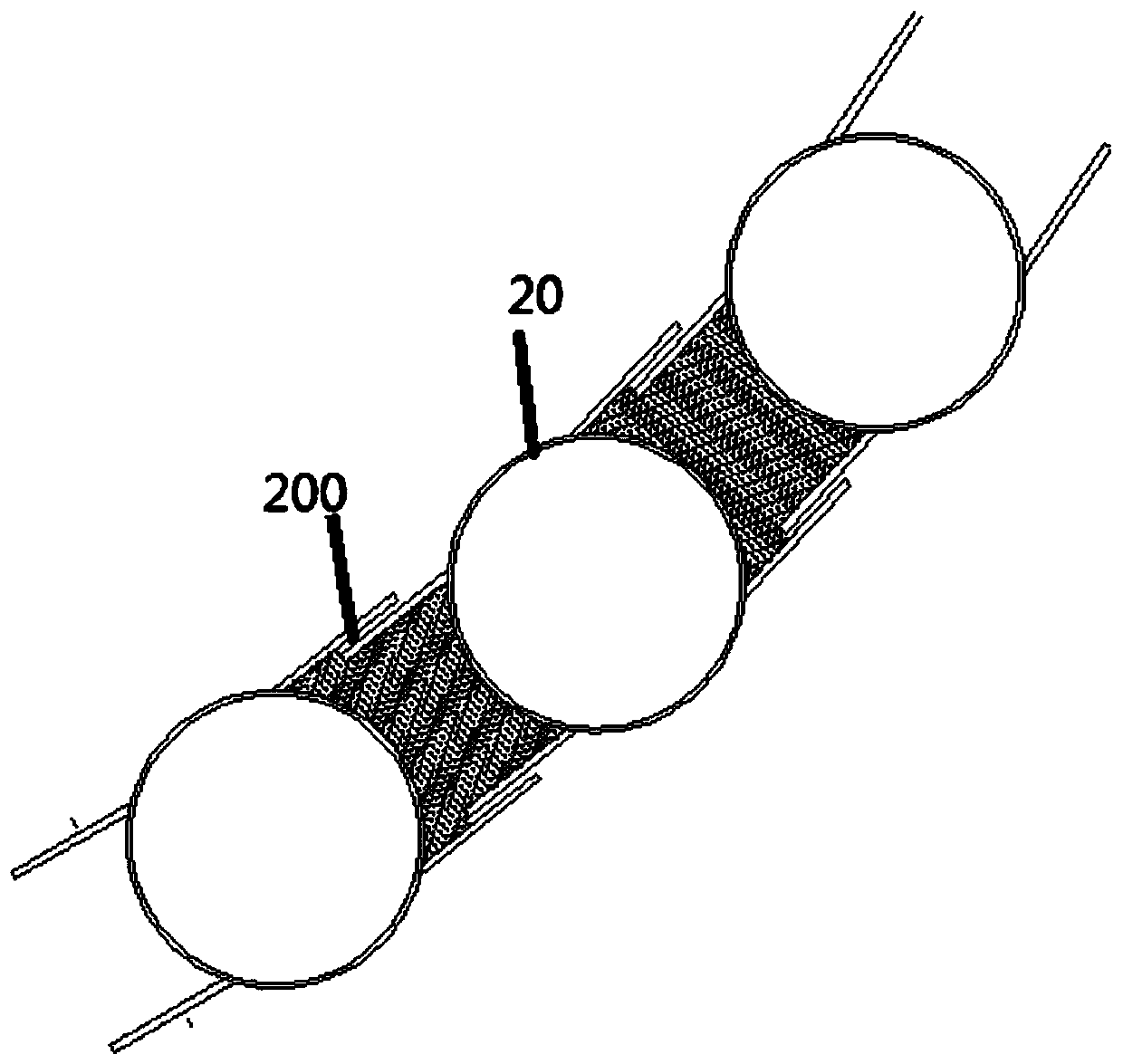
[0043] A plurality of steel pipe piles 20 extend into the soil from between two steel members, and are arranged along the ring surface of the steel structure ring beam to enclose a construction area;

[0044] The support ring 30 is located in the construction area and at least part of its outer wall is in contact with the side wall of the steel pipe pile 20 .

[0045] Specifically, the diameter of the steel structure ring beam 10 is adjustable, and can be designed according to the area of ​​the soil, not only can limit the position of the polluted soil, but also can position the steel pipe pile 20, so as to facilita...

Embodiment 2

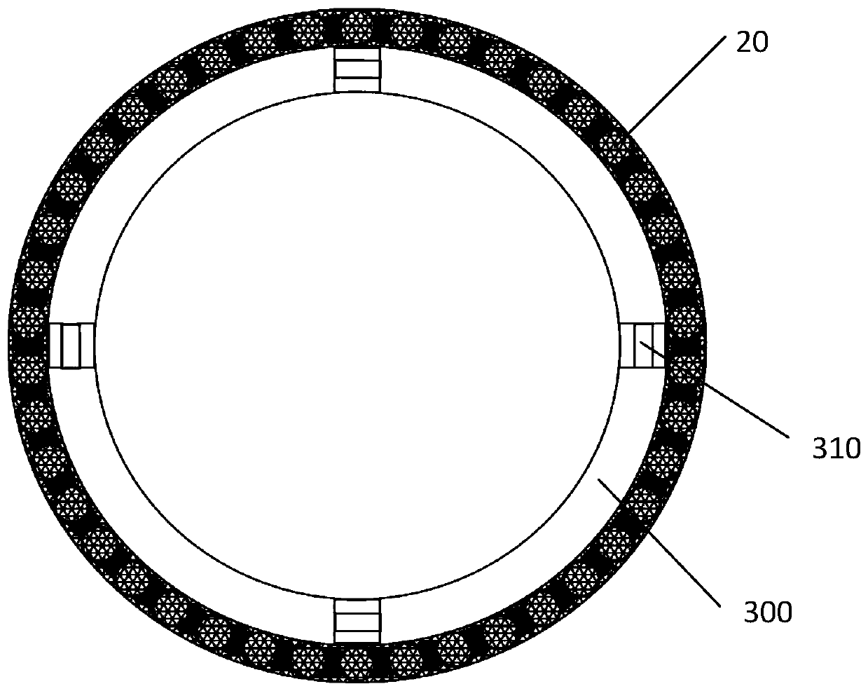
[0055] Such as Figure 4 As shown, the containment device also includes a plurality of jacks 310, and the jacks 310 include a fixed end and a telescopic end connected to each other, the telescopic end can be extended or shortened relative to the fixed end, and the fixed end and the fixed end The outer wall of the support ring 30 is connected, and the telescopic end protrudes radially to abut against the side wall of the steel pipe pile 20 . In this embodiment, the jack 310 is connected with an axial force servo system to adjust the force of the supporting ring 30 . The jack 310 is controlled by the axial force servo system to apply reaction force to the enclosure structure, changing the passive support mode into active control and changing the working principle of the traditional support system. It can be understood that when the axial force servo system receives the stress generated by the soil outside the construction area into the construction area, the axial force servo s...


PUM


Abstract

The invention provides an enclosure device used for soil enclosure. The enclosure device comprises a steel structure ring beam, a plurality of steel pipe piles and a supporting ring, wherein the steelstructure ring beam is arranged in soil and with the upper surface flush with the surface of the soil, and the steel structure ring beam comprises two circular steel components which are concentrically arranged; the steel pipe piles stretch into the soil between the two steel components and are arranged along the ring surface of the steel structure ring beam to enclose a construction area; and the supporting ring is located in the construction area and with at least part of the outer wall connected with the side wall of each steel pipe pile. The construction area is effectively reinforced through the supporting ring, so that stability of the enclosure device is improved. The invention further provides a soil remediation method utilizing the enclosure device on the basis of the enclosure device. The enclosure device is used for enclosing the soil so as to remove the soil, so that the problem of secondary pollution easily caused by volatile pollutants, toxic and harmful gas, soil particles containing pollutants and raised dust in the excavation process is solved.

Description

technical field [0001] The invention relates to the technical field of construction engineering, in particular to an enclosure device and a soil restoration method. Background technique [0002] In recent years, the problem of site pollution in my country has gradually become prominent, posing a serious threat to the ecological environment, food safety and human health. Contaminated site restoration projects have been carried out across the country to ensure environmental quality and human health. Generally speaking, the remediation technology of contaminated sites can be divided into in-situ remediation technology and ex-situ remediation technology according to the remediation site. [0003] The in-situ remediation technology refers to the technology of directly remediating the contaminated site without moving the soil. The commonly used in-situ remediation technology is to inject a leaching agent into the soil for chemical remediation, but the injection of the leaching age...

Claims


Application Information

Patent Timeline
IPC IPC(8): E02D5/02E02D5/03E02D31/06
CPCE02D5/02E02D5/03E02D31/06
Inventor 姜小强赵培朱建平赵琛夏建坤周云佳
Owner SHANGHAI MECHANIZED CONSTR GRP
Learn More