
Transformer electric appliance cabinet

A technology for electrical cabinets and transformers, applied in transformer/inductor housing, transformer/inductor cooling, transformer/inductor components, etc., can solve the problems of transformer damage, reduced work efficiency, transformer insulation aging, etc., to improve the flow rate and flow rate, reducing losses, reducing the effect of internal temperature

Inactive Publication Date: 2020-06-23
SHANDONG INST FOR PROD QUALITY INSPECTION
View PDF9 Cites 4 Cited by
  • Summary
  • Abstract
  • Description
  • Claims
  • Application Information

AI Technical Summary

Problems solved by technology

[0002] The electrical components in the transformer electrical cabinet often generate a lot of heat due to the work of the electric load during work. The heat generated can easily cause the insulation of the transformer to age and the work efficiency to decrease. When the heat generated exceeds the heat resistance level of the transformer Finally, it is very easy to cause the transformer to be damaged due to high temperature. Therefore, the heat effect of the transformer electrical cabinet fan currently used is not good, and accidents often occur due to high temperature damage, and the electrical cabinet is easy to catch fire and cause losses.

Method used


Image

  • Transformer electric appliance cabinet
  • Transformer electric appliance cabinet
  • Transformer electric appliance cabinet

Examples


Embodiment Construction

[0018] The preferred embodiments of the present invention will be described in detail below in conjunction with the accompanying drawings, so that the advantages and features of the present invention can be more easily understood by those skilled in the art, so as to define the protection scope of the present invention more clearly.

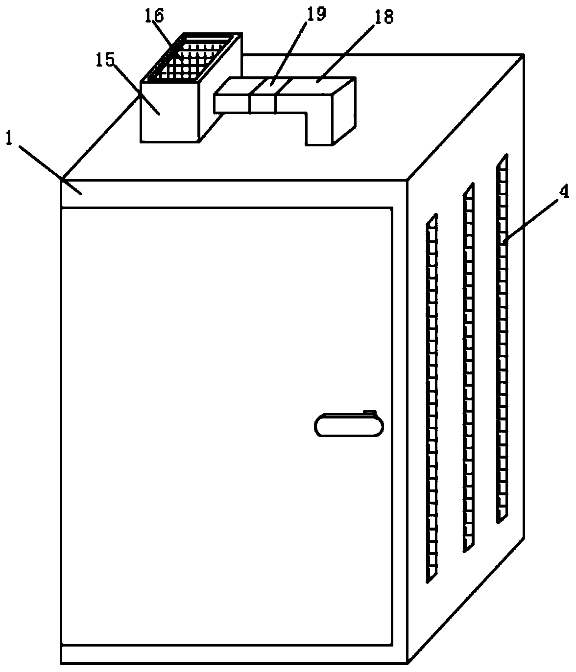
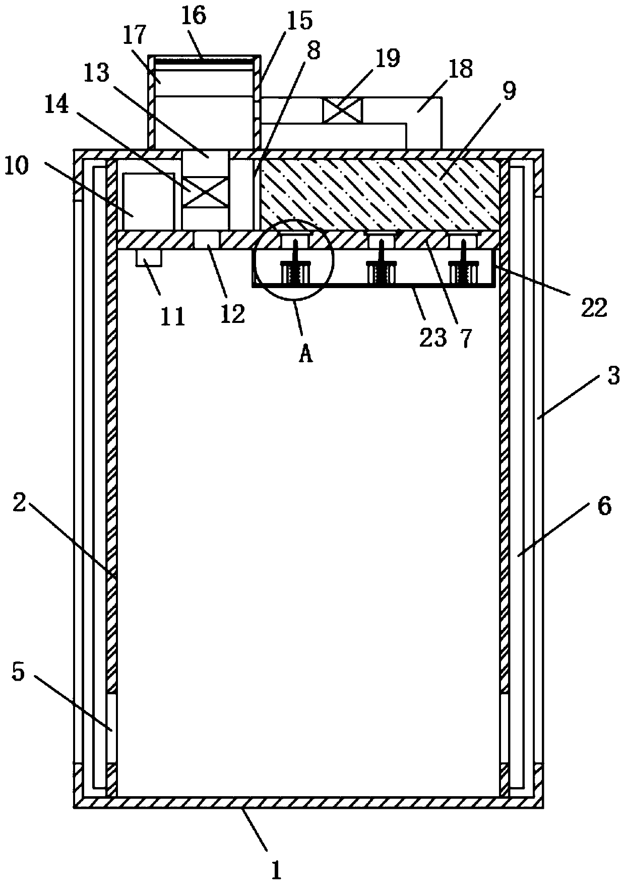
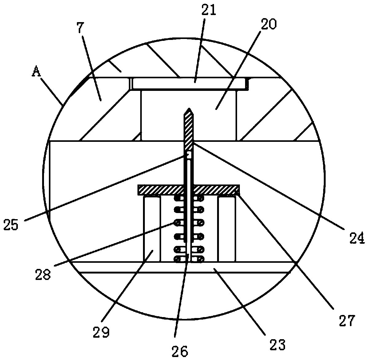
[0019] refer to figure 1 and figure 2 As shown, the present invention provides a transformer electrical cabinet, which includes a cabinet body 1, and heat absorbing plates 2 are fixedly installed on both sides of the inside of the cabinet body 1, and a cooling chamber is formed between the heat absorbing plate 2 and the inner wall of the cabinet body 1, and the cabinet body 1 Both outer surfaces are provided with a plurality of heat dissipation notches 3, the heat dissipation notches 3 run through the heat dissipation cavity, the lower end of the heat absorbing plate 2 is provided with an air outlet 5, the upper end of the cabinet body 1 is fixe...


PUM


Abstract

The invention discloses a transformer electric appliance cabinet, the cabinet comprises a cabinet body, heat absorbing plates are fixedly installed on the two sides of the interior of the cabinet body, and the two outer side surfaces of the cabinet body are respectively provided with a plurality of heat dissipation notches. A supporting plate is fixedly mounted at the upper end in the cabinet body, and the upper surface of the cabinet body is fixedly provided with a dustproof box at the position of one cavity. A fan is fixedly mounted in the dustproof box, the other chamber at the upper end inthe cabinet body is filled with dry powder, crushing mechanisms used for crushing the glass cover plate are installed on the upper surfaces of the pull rods and located at the installation openings.The heat absorbing plates are arranged on the two sides in the cabinet body, heat in the cabinet body can be absorbed so as to exchange heat with outside air, the temperature in the cabinet body can be reduced, the temperature can be detected through the temperature sensor, and when the temperature reaches a limit value, the crushing rod can crush the glass cover plate, so that dry powder is sprayed into the cabinet body through the mounting opening, the fire extinguishing effect is achieved, and losses caused by fire disasters are reduced.

Description

technical field [0001] The present invention relates to the technical field of electrical cabinets, and more specifically relates to a transformer electrical cabinet. Background technique [0002] The electrical components in the transformer electrical cabinet often generate a lot of heat due to the work of the electric load during work. The heat generated can easily cause the insulation of the transformer to age and the work efficiency to decrease. When the heat generated exceeds the heat resistance level of the transformer Finally, it is very easy to cause the transformer to be damaged due to high temperature. Therefore, the thermal effect of the transformer electrical cabinet fan currently used is not good, and accidents often occur due to high temperature damage, and the electrical cabinet is easy to catch fire and cause losses. Contents of the invention [0003] The purpose of the present invention is to provide a transformer electrical cabinet. [0004] In order to ...

Claims


Application Information

Patent Timeline
Patent Type & Authority Applications(China)
IPC IPC(8): H01F27/02H01F27/08A62C31/00A62C3/16A62C37/00
CPCA62C3/16A62C31/00A62C37/00H01F27/025H01F27/085
Inventor 张培英原新伟尹环环
Owner SHANDONG INST FOR PROD QUALITY INSPECTION
Learn More