Heat dissipation and ventilation type power distribution cabinet for communication engineering

A communication engineering and air-permeable technology, which is applied in the direction of electrical components, substation/switch arrangement details, substation/switchgear cooling/ventilation, etc. Damage and other problems, to achieve a better cooling effect, accelerate the flow of airflow, and easy to use

Inactive Publication Date: 2020-06-23
山东鼎盛电气设备有限公司
View PDF0 Cites 7 Cited by
  • Summary
  • Abstract
  • Description
  • Claims
  • Application Information

AI Technical Summary

Problems solved by technology

[0003] The power of some power distribution cabinets is relatively large, and these power distribution cabinets are easily damaged due to overheating during use, causing saf

Method used


Image

  • Heat dissipation and ventilation type power distribution cabinet for communication engineering
  • Heat dissipation and ventilation type power distribution cabinet for communication engineering
  • Heat dissipation and ventilation type power distribution cabinet for communication engineering

Examples


Embodiment 1

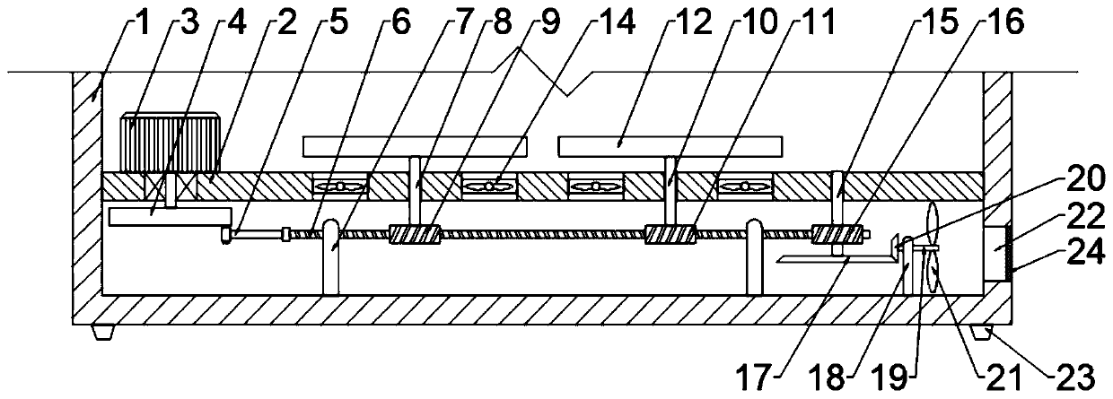
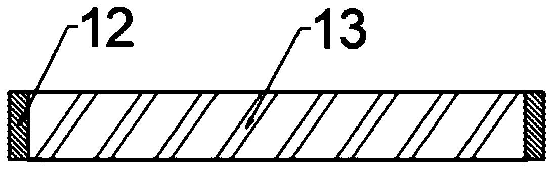
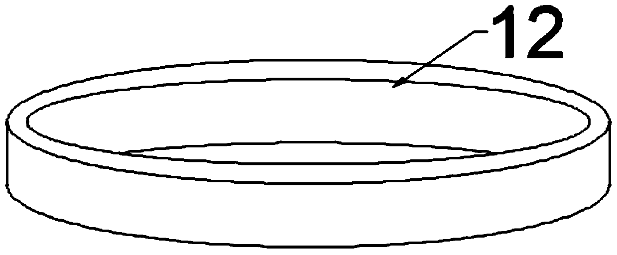
[0022] Example 1: Please refer to Figure 1-3 , a heat dissipation and breathable power distribution cabinet for communication engineering, comprising a cabinet body 1, a horizontal fixing plate 2 is fixedly connected to the inner side of the cabinet body 1, a motor 3 is fixedly connected to the upper left of the horizontal fixing plate 2, and the output end of the motor 3 runs through the cabinet body 1 is connected with a turntable 4, the right side of the turntable 4 is rotated and connected with a transmission pendulum 5, and the right side of the transmission pendulum 5 is connected with a transmission rack 6, and the inner bottom of the cabinet 1 is fixedly connected with a guide bracket 7, and the transmission gear Bar 6 is slidingly connected with guide bracket 7;

[0023] Turn on the motor 3 during use, the rotation of the motor 3 drives the turntable 4 to rotate, and the rotation of the turntable 4 can drive the drive rack 6 to move left and right through the transmi...

Embodiment 2

[0036] Example 2: Please refer to Figure 1-3 , a heat dissipation and breathable power distribution cabinet for communication engineering, comprising a cabinet body 1, a horizontal fixing plate 2 is fixedly connected to the inner side of the cabinet body 1, a motor 3 is fixedly connected to the upper left of the horizontal fixing plate 2, and the output end of the motor 3 runs through the cabinet body 1 is connected with a turntable 4, the right side of the turntable 4 is rotated and connected with a transmission pendulum 5, and the right side of the transmission pendulum 5 is connected with a transmission rack 6, and the inner bottom of the cabinet 1 is fixedly connected with a guide bracket 7, and the transmission gear Bar 6 is slidingly connected with guide bracket 7;

[0037] Turn on the motor 3 during use, the rotation of the motor 3 drives the turntable 4 to rotate, and the rotation of the turntable 4 can drive the drive rack 6 to move left and right through the transmi...


PUM


Abstract

The invention discloses a heat dissipation and ventilation type power distribution cabinet for communication engineering, and relates to a power distribution cabinet. The power distribution cabinet comprises a cabinet body. A horizontal fixing plate is fixedly connected to the inner side of the cabinet body; a motor is fixedly connected to the upper left portion of the horizontal fixing plate; theoutput end of the motor runs through the cabinet body and is connected with a rotary disc; the right side of the rotary disc is rotationally connected with a transmission swing rod; the right side ofthe transmission swing rod is rotationally connected with a transmission toothed bar; guide supports are fixedly connected to the bottom in the cabinet body in a bilateral symmetry mode; the transmission toothed bar is slidably connected with the guide supports; a first longitudinal shaft is rotationally connected to the left side of the horizontal fixing plate; and a first transmission gear is fixedly connected to the bottom of the first longitudinal shaft and engaged with the transmission toothed bar. The cabinet is simple in structure, is driven by the motor during use, achieves the reciprocating rotation of the rotating guide ring through the transmission of the transmission toothed bar, can guide air to different positions, reduces the temperature of air in the cabinet body to the maximum degree, can accelerate the inflow of air flow through the cooperation with spiral fan blades, and is better in cooling effect.

Description

technical field [0001] The invention relates to a power distribution cabinet, in particular to a heat dissipation and ventilation type power distribution cabinet for communication engineering. Background technique [0002] Power distribution cabinets (boxes) are divided into power distribution cabinets (boxes), lighting distribution cabinets (boxes), and metering cabinets (boxes), which are the final equipment of the power distribution system. The power distribution cabinet is a general term for the motor control center. The power distribution cabinet is used in the occasions where the load is relatively scattered and there are few circuits; the motor control center is used in the occasions where the load is concentrated and there are many circuits. They distribute the electric energy of a certain circuit of the upper-level power distribution equipment to the nearest load. This level of equipment shall provide protection, monitoring and control of the load. [0003] The p...

Claims


Application Information

Patent Timeline
IPC IPC(8): H02B1/56
CPCH02B1/565
Inventor 王庆普卓成林李巧莲郭化欣黄楠
Owner 山东鼎盛电气设备有限公司
Why Eureka
Try Eureka