High-temperature-resistant self-watering flowerpot

A technology for preventing high temperature and flower pots, applied in automatic watering devices, container cultivation, gardening, etc., can solve the problems of inability to live experience, reduced oxygen content, and plants are prone to water shortage, and achieve the effect of increasing life experience.

Active Publication Date: 2020-06-26
南京望天科技有限公司
View PDF6 Cites 2 Cited by
  • Summary
  • Abstract
  • Description
  • Claims
  • Application Information

AI Technical Summary

Problems solved by technology

[0003] When the temperature is high in summer, the water in the soil in the flowerpot evaporates quickly, which makes the plants in the flowerpot easily lack water and affects the normal growth of the plants. At present, in order to avoid trouble in summer, most people water the flowerpot If you pour too much water at one time, the oxygen content in the soil will decrease, and the root system will have difficulty breathing, which will easily lead to rotten roots and affect the normal growth of plants. Bring a good life experience

Method used


Image

  • High-temperature-resistant self-watering flowerpot
  • High-temperature-resistant self-watering flowerpot
  • High-temperature-resistant self-watering flowerpot

Examples


Embodiment 1

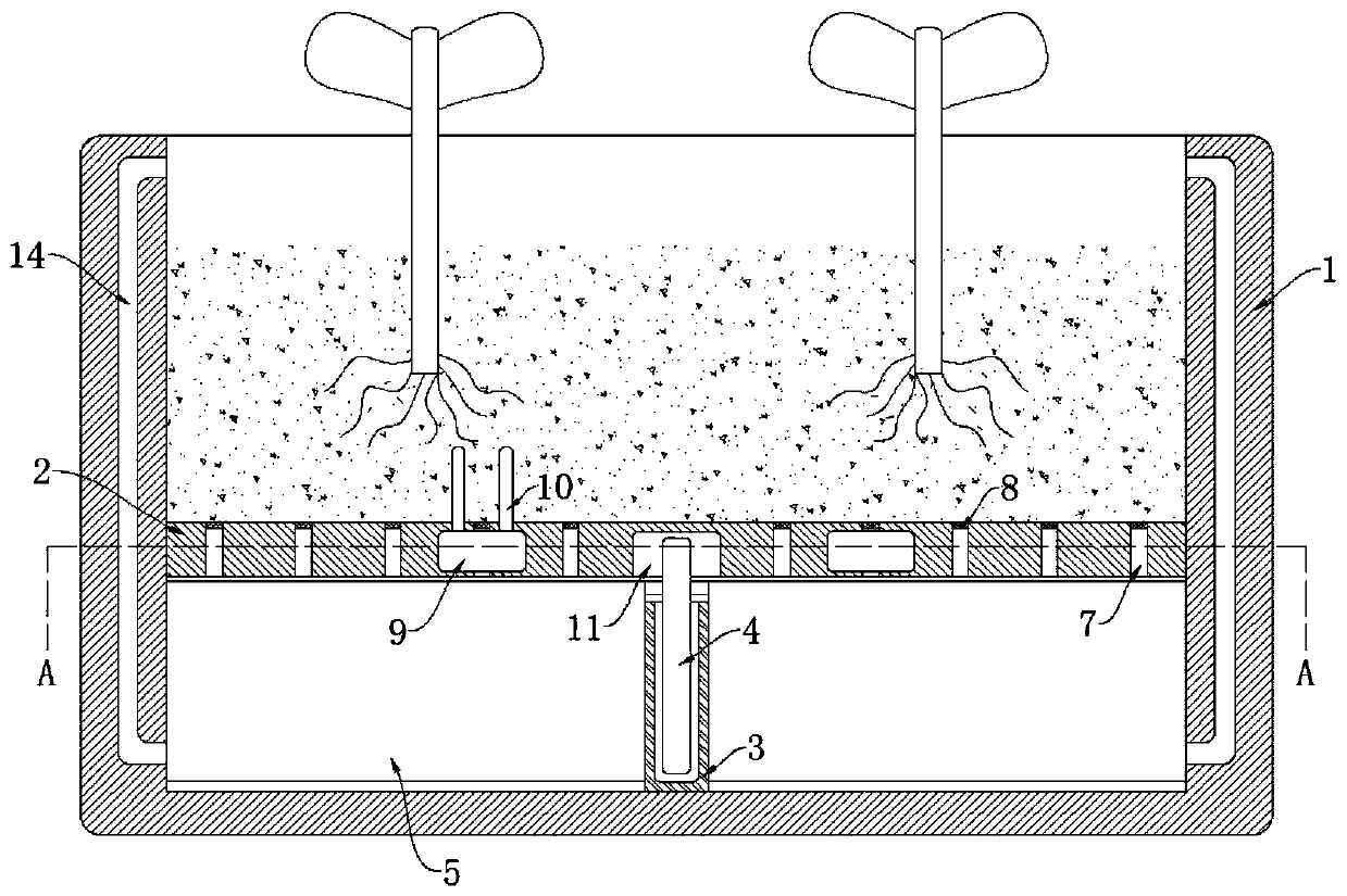
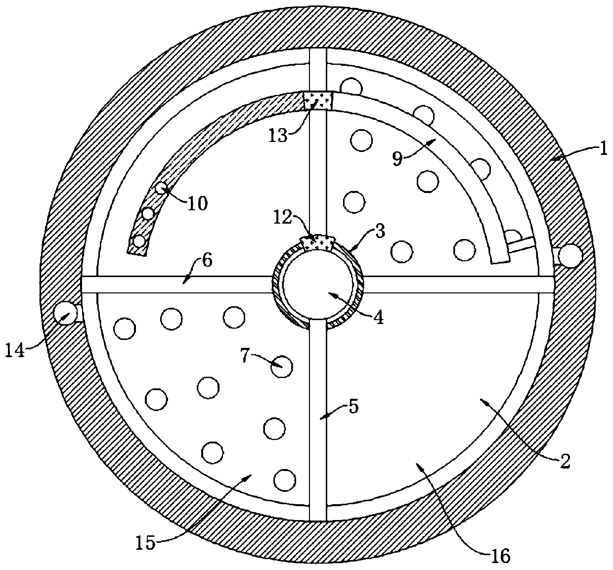
[0023] refer to Figure 1-2 , a self-watering anti-high temperature flower pot, comprising a pot body 1, the inner wall of the pot body 1 is fixedly connected with a baffle plate 2, the inner bottom of the pot body 1 is fixedly connected with a cylinder 3, and the inner wall of the cylinder 3 is rotatably connected with a vertical rod 4. The side wall of the vertical rod 4 is fixedly connected with the first partition 5 through the connecting rod, and the first partition 5 is sealed and slidingly connected with the side wall of the cylinder 3 and the inner wall of the basin body 1, and the opposite side wall of the cylinder 3 is fixedly connected with the second partition. Two partitions 6, the first partition 5, the second partition 6 and the inner wall of the basin body 1 form the first chamber 15 and the second chamber 16, and the first chamber 15 is filled with nutrient solution, further, the basin body 1. The side wall is provided with a liquid inlet connected to the firs...

Embodiment 2

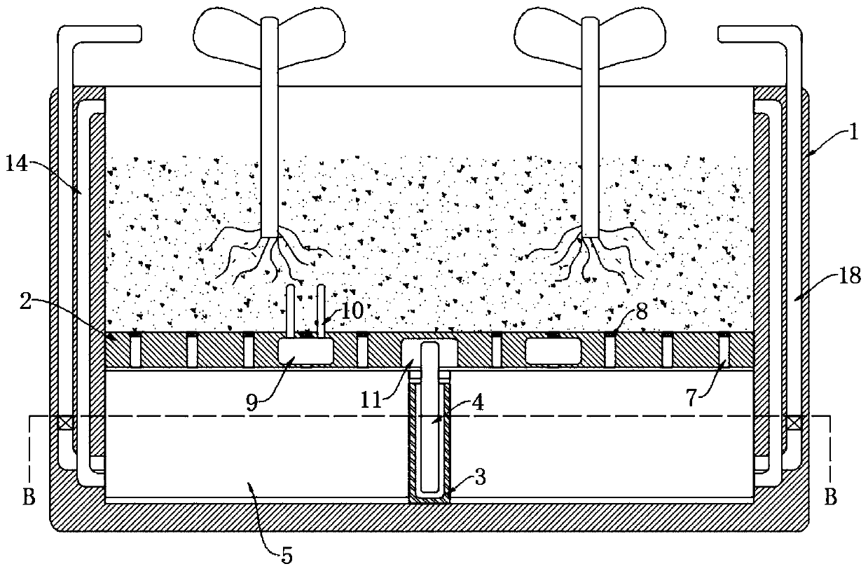
[0027] refer to Figure 3-4 Different from Embodiment 1, the inner wall of the second chamber 16 is fixedly connected with a flexible air bag 17, and the opposite side wall of the basin body 1 is connected with a one-way air jet pipe 18. The dust on the air is blown off, and the lower end of the one-way jet pipe 18 communicates with the side wall of the telescopic air bag 17, and the side wall of the telescopic air bag 17 is connected with a one-way suction pipe 19. It should be noted that the one-way jet pipe 18 and the one-way suction pipe The trachea 19 can realize its function by installing a one-way valve on its inner wall.

[0028] In this embodiment, when the evaporating liquid is heated and vaporized and expanded, the vertical rod 4 drives the first partition plate 5 to rotate, so that the volume of the first chamber 15 decreases, and the volume of the second chamber 16 increases, so that it is compatible with the second chamber. The telescopic airbag 17 fixedly conne...


PUM


Abstract

The present invention discloses a high-temperature-resistant self-watering flowerpot. The flowerpot comprises a pot body; the inner wall of the pot body is fixedly connected with a baffle; the inner bottom of the pot body is fixedly connected with a cylinder; the inner wall of the cylinder is rotationally connected with a vertical rod; the side wall of the vertical rod is fixedly connected with afirst partition plate through a connecting rod; and the baffle is provided with a driving device for driving the vertical rod to rotate. When the temperature in the pot body is increased, an evaporated liquor is heated to be expanded for pushing a magnetic sliding plug to slide in the inner wall of an arc-shaped cavity, and a magnet drives the vertical rod to rotate, so that space of a first chamber is reduced, a nutrient solution in the first chamber is extruded into a liquid outlet cavity and flows out from the liquid outlet cavity to wet soil in the pot body, and the situation that people need to add water to the soil without stop is avoided; and when the volume of a second chamber is reduced, gas in a telescopic gasbag is ejected by a one-way gas ejector pipe to clean dust on a plant,thereby avoiding influence on plant growth due to accumulation of relatively much dust on the plant.

Description

technical field [0001] The invention relates to the technical field of flower pots, in particular to a self-watering heat-resistant flower pot. Background technique [0002] A flowerpot is a container for planting flowers, which is in the shape of a rounded table or a chamfered table with a large mouth and a small bottom. [0003] When the temperature is high in summer, the water in the soil in the flowerpot evaporates quickly, which makes the plants in the flowerpot easily lack water and affects the normal growth of the plants. At present, in order to avoid trouble in summer, most people water the flowerpot If you pour too much water at one time, the oxygen content in the soil will decrease, and the root system will have difficulty breathing, which will easily lead to rotten roots and affect the normal growth of plants. Bring a good life experience. [0004] For this reason, we propose a self-watering anti-high temperature flower pot to solve the above problems. Content...

Claims


Application Information

Patent Timeline
Patent Type & Authority Applications(China)
IPC IPC(8): A01G9/02A01G27/02A01G7/06A01C23/02
CPCA01G9/02A01G27/02A01G7/06A01C23/023
Inventor 王传成
Owner 南京望天科技有限公司
Why Eureka
Try Eureka