Method and device for monitoring abrasion state of tool based on energy analysis of wavelet packets

A tool wear and energy analysis technology, used in manufacturing tools, measuring/indicating equipment, metal processing machinery parts, etc., can solve problems such as complex mechanical environment and thermal environment, difficult measurement, etc. Effect

Inactive Publication Date: 2020-06-26
CIVIL AVIATION UNIV OF CHINA
View PDF6 Cites 8 Cited by
  • Summary
  • Abstract
  • Description
  • Claims
  • Application Information

AI Technical Summary

Problems solved by technology

Aircraft composite material automatic processing machine tools usually operate in an environment with high speed and cutting dust. Tool wear occurs in the complex mechanical environment and thermal environment during the cutting process. It has strong irregularities and is difficult to measure by traditional means.

Method used


Image

  • Method and device for monitoring abrasion state of tool based on energy analysis of wavelet packets
  • Method and device for monitoring abrasion state of tool based on energy analysis of wavelet packets
  • Method and device for monitoring abrasion state of tool based on energy analysis of wavelet packets

Examples


Embodiment 1

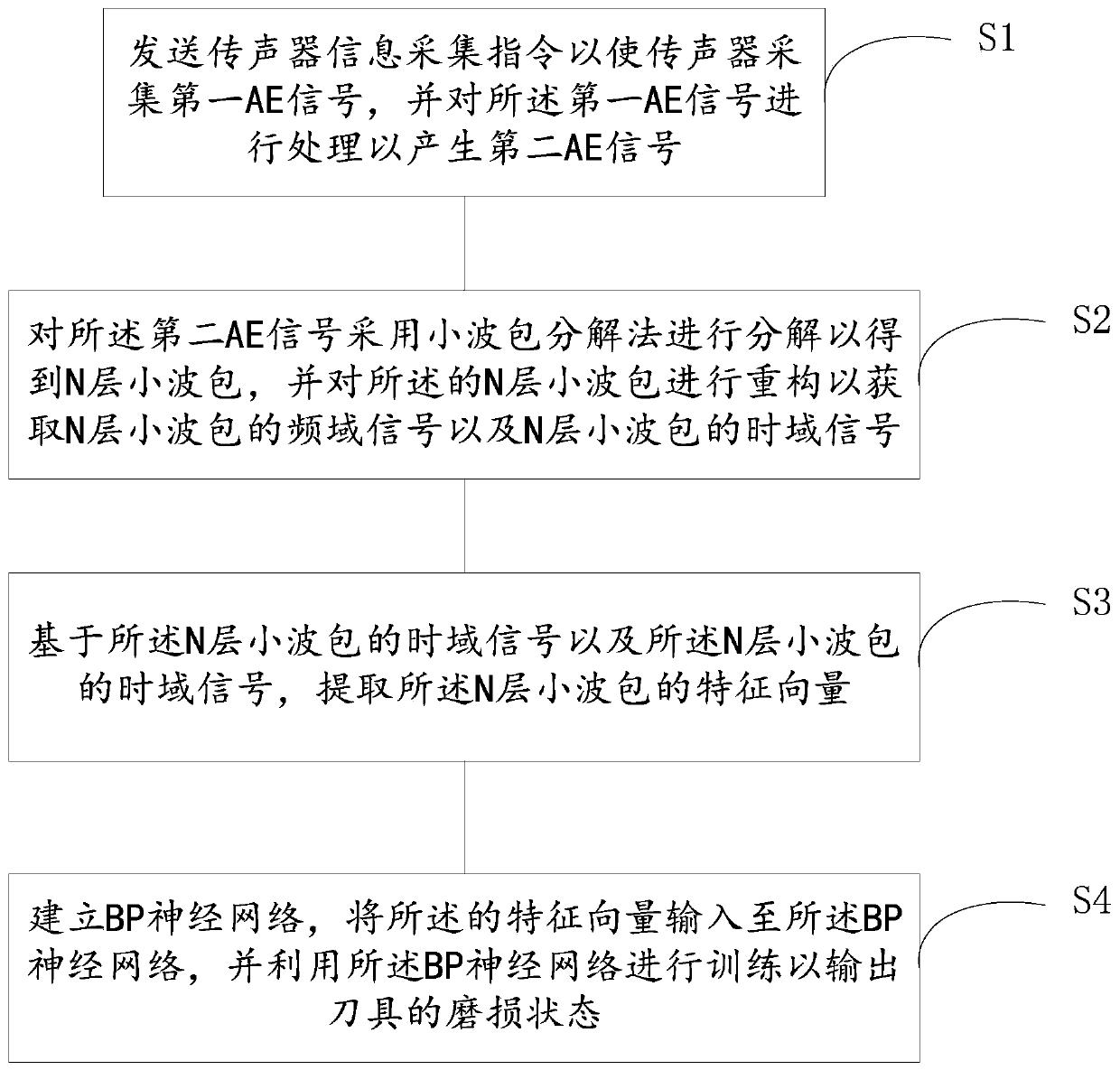
[0077] Such as figure 1 As shown, the first embodiment of the present invention provides a tool wear state monitoring method based on wavelet packet energy analysis, which is applied to a server and includes:

[0078] S1: Send a microphone information collection instruction to enable the microphone to collect a first AE signal, and process the first AE signal to generate a second AE signal;

[0079] Specifically, since the first AE signal is a time-varying and weak acoustic signal, the first AE signal needs to be processed, which specifically includes the steps of filtering, amplifying, and converting analog signals to digital signals;

[0080] Preferably, step S1 includes the following steps:

[0081] Amplifying and filtering the first AE signal, and converting the amplified and filtered first AE signal into an analog signal to generate the second AE signal;

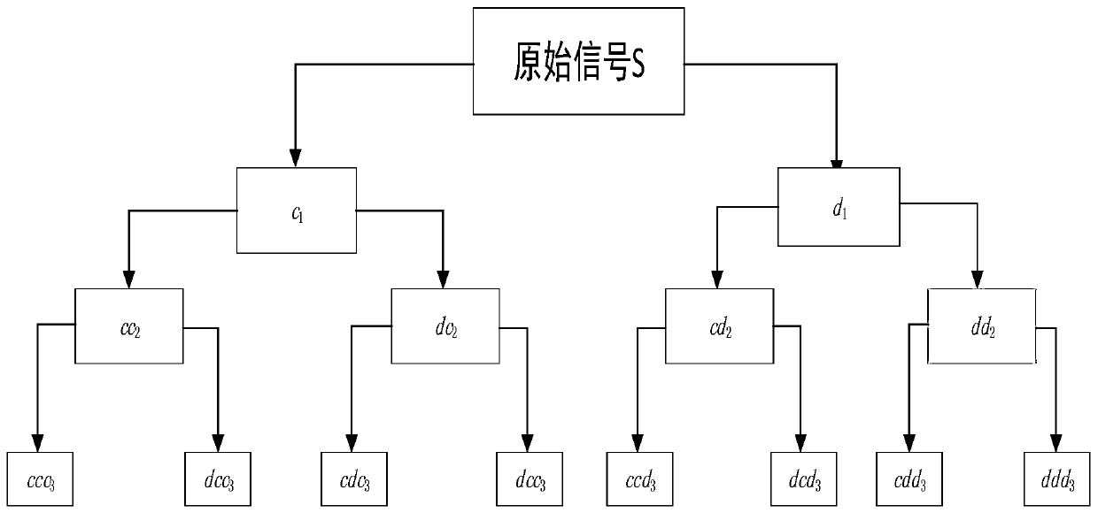
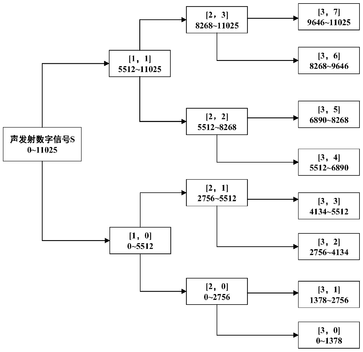
[0082] S2: Decompose the second AE signal using a wavelet packet decomposition method to obtain an N-layer wavelet packet, and...

Embodiment 2

[0142] The second embodiment of the present invention provides a tool wear state monitoring device based on wavelet packet energy analysis, including:

[0143] Signal generation module: used to send a microphone information collection instruction so that the microphone collects a first AE signal, and processes the first AE signal to generate a second AE signal;

[0144] Signal processing module: used to decompose the second AE signal using the wavelet packet decomposition method to obtain an N-layer wavelet packet, and reconstruct the N-layer wavelet packet to obtain the frequency domain signal of the N-layer wavelet packet, and Time domain signal of N-layer wavelet packet;

[0145] Feature vector extraction module: used to extract the feature vector of the N-layer wavelet packet based on the time-domain signal of the N-layer wavelet packet and the time-domain signal of the N-layer wavelet packet;

[0146] Neural network building module: establish a BP neural network, input the featur...


PUM


Abstract

The invention provides a method and device for monitoring an abrasion state of a tool based on energy analysis of wavelet packets, and relates to the technical field of tool abrasion detection. The method comprises the steps that a microphone information collection instruction is sent to enable a microphone to collect a first AE signal, and the first AE signal is processed to generate a second AEsignal; the second AE signal is decomposed through a wavelet packet decomposition method to obtain the N layers of wavelet packets, and the N layers of wavelet packets are reconstructed to obtain frequency domain signals and time domain signals of the N layers of wavelet packets; based on the frequency domain signals and the time domain signals of the N layers of wavelet packets, characteristic vectors of the N layers of wavelet packets are extracted; and a BP neural network is established, the characteristic vectors are input into the BP neural network, and training is conducted through the BP neural network so as to output the abrasion state of the tool. By utilizing the method and device provided by the invention, the abrasion state of the composite material tool can be effectively monitored, and thus the quality of aircraft composite material machined parts is guaranteed.

Description

Technical field [0001] The invention relates to the technical field of tool wear detection, in particular to a tool wear state monitoring method and device based on wavelet packet energy analysis. Background technique [0002] With the rapid development of aerospace technology, composite materials have gradually replaced traditional single-component materials and have been widely used in aircraft manufacturing. Composite materials are multiphase new solid materials formed by processing two or more substances with different physical and chemical properties through a composite process. It is on the basis of retaining the advantages of the original component materials, through the material design, the performance of each component material is related to each other and complements each other, so as to obtain new superior performance. [0003] Composite materials have many advantages: light weight, high strength, good designability, good process performance and outstanding fatigue resi...

Claims


Application Information

Patent Timeline
Patent Type & Authority Applications(China)
IPC IPC(8): B23Q17/09
CPCB23Q17/0957
Inventor 刘晓琳马丽霞
Owner CIVIL AVIATION UNIV OF CHINA
Why Eureka
Try Eureka