
Shock-absorbing member and washing machine

A technology for washing machines and shock parts, which is applied in the field of washing equipment, can solve problems such as inability to adjust the damping force, single damping force, and large vibration noise, so as to improve the stability of shock absorption, ensure the stability of the whole machine, and reduce vibration noise. Effect

Pending Publication Date: 2020-06-26
QINGDAO HAIER DRUM WASHING MACHINE
View PDF6 Cites 1 Cited by
  • Summary
  • Abstract
  • Description
  • Claims
  • Application Information

AI Technical Summary

Problems solved by technology

[0004] However, since the above-mentioned existing shock absorbers can only provide a constant single damping force to the water storage cylinder, the damping force cannot be adjusted during the entire working process of the washing machine, so that many shocks will be generated due to the simplification of the damping force in the entire working condition of the washing machine. question
[0005] For example: when the water tank is running at high speed to perform the dehydration program, the suspended water tank will generate high-frequency and small vibrations, and the shock absorber will vibrate along with it, resulting in a constant damping force that is always pushing and pulling, so as to transmit the vibration of the water tank to the washing machine shell, there will be a problem of excessive vibration and noise
[0006] Another example: when the water tank is started at a low speed, the suspended water tank will generate low-frequency and large-scale vibrations due to problems such as uneven internal balance, and the shock absorber will vibrate along with it. If the shock absorber can only produce a single damping force, it will As a result, when the amplitude of the water tank is too large, it cannot meet the deviation correction function, which in turn causes the problem of excessive amplitude of the washing machine body and even movement

Method used


Image

  • Shock-absorbing member and washing machine
  • Shock-absorbing member and washing machine
  • Shock-absorbing member and washing machine

Examples


Embodiment 1

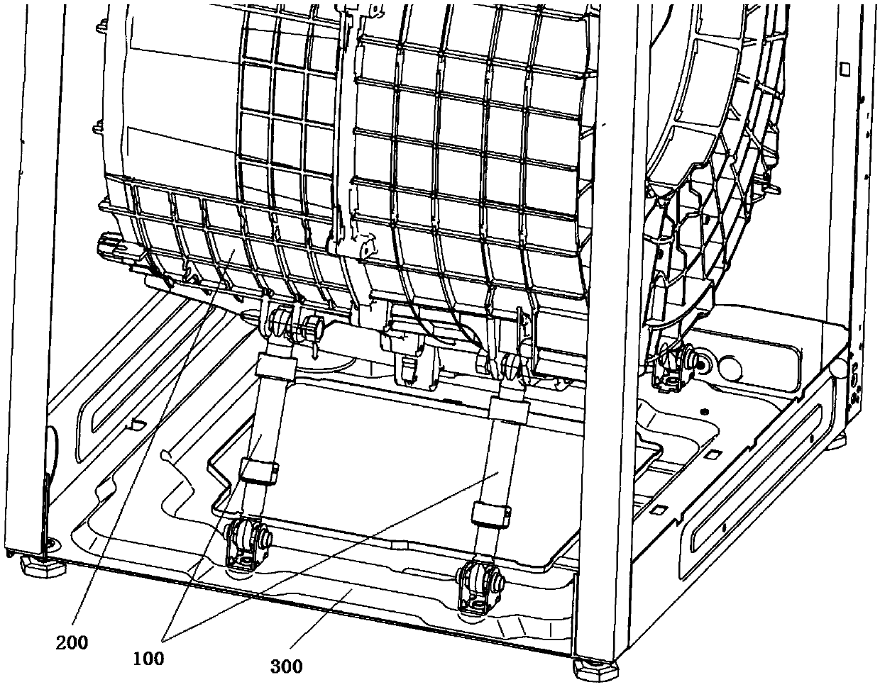
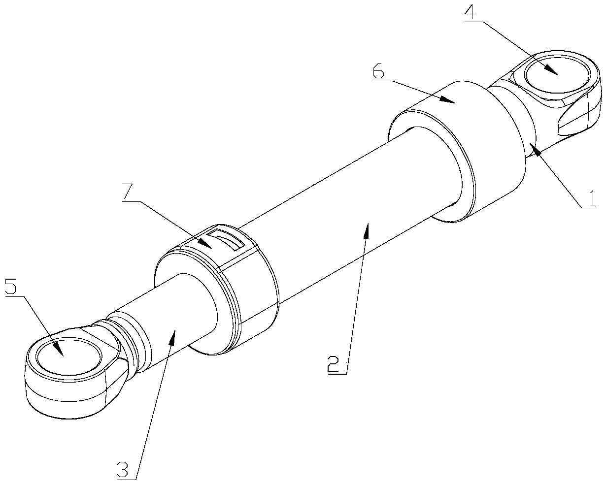
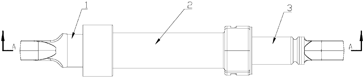
[0050] Such as Figure 2 to Figure 4 As shown, this embodiment introduces a shock absorber for a washing machine, which includes: a first-stage shock absorber 1, a second-stage shock absorber 2, and a third-stage shock absorber that are formed of a sleeve structure and inserted in sequence. 3. The lower end of the primary shock absorbing rod 1 is inserted from the upper end of the secondary shock absorbing rod 2, the upper end of the third stage shock absorbing rod 3 is inserted from the lower end of the secondary shock absorbing rod 2, and damping members are respectively provided at the two sockets.

[0051] By setting the shock absorbing rods which are composed of sleeve structures and inserted into each other in sequence, the adjacent shock absorbing rods are radially limited through the joints, and the vibration transmitted by the water tank acts on the plugging of the shock absorbing rods. In the direction, the damping members at the joints of the adjacent shock absorbin...

Embodiment 2

[0060] The difference between this embodiment and the above-mentioned embodiment 1 is: as Figure 5 As shown, in this embodiment, the damping structure at the insertion joint of the primary shock absorbing rod 1 and the secondary shock absorbing rod 2 is composed of a hydraulic damping structure and / or a pneumatic damping structure.

[0061] Such as Figure 5 As shown, in this embodiment, the upper end of the secondary shock absorbing rod 2 is correspondingly inserted into the annular cavity 6 protruding from the lower end of the primary shock absorbing rod 1. The lower side of the annular cavity 6 is provided with a circle of annular gaps, and the annular cavity 6 The opening of the gap and the joint of the secondary damping rod 2 are sealed to form a closed chamber; the end of the secondary shock absorbing rod 2 inserted into the annular cavity 6 is provided with a radially protruding ring An annular rib 8, so that the joint of the secondary shock absorber rod 2 and the pri...

Embodiment 3

[0066] The difference between this embodiment and the above-mentioned embodiment 1 is: as Figure 6 As shown, in this embodiment, the damping structure at the insertion joint of the primary shock absorbing rod 1 and the secondary shock absorbing rod 2 is composed of a shock absorbing spring.

[0067] Such as Figure 6 and Figure 7 As shown, in this embodiment, the upper end of the secondary shock absorbing rod 2 is correspondingly inserted into the annular cavity 6 protruding from the lower end of the primary shock absorbing rod 1. The lower side of the annular cavity 6 is provided with a circle of annular gaps. The upper end of the shock rod 2 is inserted into the annular cavity 6 from the opening of the annular cavity 6 . The end of the secondary damping rod 2 inserted into the annular cavity 6 is provided with a radially protruding circle of annular ribs 8, and the first spring 12 and the annular ribs are clamped between the annular ribs 8 and the upper side wall of the ...


PUM


Abstract

The invention relates to a shock-absorbing member for a washing machine. The shock-absorbing member comprises at least three segments of shock-absorbing rods, wherein various segments of shock-absorbing rods are correspondingly connected through insertion in sequence in series to form a strip-shaped shock-absorbing member; damping members are separately arranged at the insertion positions betweenthe adjacent shock-absorbing rods to provide damping force for relative movement of the shock-absorbing rods in insertion connection. The shock-absorbing member disclosed by the invention is arrangedto be of a structure that three or more segments of shock-absorbing rods are connected through insertion in sequence, and damping structures are separately arranged at the insertion positions, so thatthe shock-absorbing member can perform superimposed combined shock absorption through damping at multiple positions to provide diverse damping shock-absorbing force, so as to improve the shock-absorbing performance of the shock-absorbing member. The invention further provides a washing machine. A water basket of the washing machine is arranged in a washing machine housing through the shock-absorbing member.

Description

technical field [0001] The invention belongs to a washing machine in the field of washing equipment, and in particular relates to a shock absorber for a washing machine. Background technique [0002] With the increase in the demand for high-end laundry in the user market, the demand for noise reduction of washing machines in the market is getting higher and higher. However, due to structural limitations, a lot of noise is generated during the stretching movement of the shock absorber, and the shock absorber will transmit the vibration. The shell will cause the washing machine body to vibrate or even resonate noise, so that the user cannot get a good washing experience, and even cause the user to complain. [0003] The current washing machine shock absorbers generally consist of two shock absorbing rods inserted into each other, and a damping structure is provided between the plugged shock absorbing rods to provide damping force for the shock absorbers that can move axially w...

Claims


Application Information

Patent Timeline
IPC IPC(8): D06F37/20
CPCD06F37/20Y02B40/00
Inventor 段崇超李文伟王金凯宁骁
Owner QINGDAO HAIER DRUM WASHING MACHINE
Features
  • Generate Ideas
  • Intellectual Property
  • Life Sciences
  • Materials
  • Tech Scout
  • Unparalleled Data Quality
  • Higher Quality Content
  • 60% Fewer Hallucinations
Learn More