
Large-span suspended member construction system and construction method thereof

A large-span cantilever and component technology, which is applied in the on-site preparation of building components, building construction, and scaffolding accessories, etc., can solve the problems of I-beam self-heavy, large I-beam section selection, and increased construction costs. , to achieve the effect of shortening the construction period, simplifying the form of stress, and saving construction materials

Active Publication Date: 2020-06-26
中国建筑土木建设有限公司
View PDF6 Cites 4 Cited by
  • Summary
  • Abstract
  • Description
  • Claims
  • Application Information

AI Technical Summary

Problems solved by technology

Since the external scaffolding system is erected from the bottom of the building foundation, the backfill construction cannot be carried out before the external scaffolding system is removed, which seriously restricts the construction period of the backfilling soil; as the external scaffolding system occupies the construction of the external wall and the waterproof protection of the external wall, there is leakage of the external wall. Leakage risk; In addition, the cantilevered components adopt the basic structure form of cantilevered I-beam, the section of I-beam is selected larger, the weight of I-beam is larger, it is not easy to assemble and dismantle, which greatly increases the construction cost

Method used


Image

  • Large-span suspended member construction system and construction method thereof
  • Large-span suspended member construction system and construction method thereof

Examples


Embodiment Construction

[0018] Hereinafter, embodiments of the large-span cantilever member construction system and construction method thereof of the present invention will be described with reference to the accompanying drawings.

[0019] The examples described here are specific specific implementations of the present invention, and are used to illustrate the concept of the present invention. They are all explanatory and exemplary, and should not be construed as limiting the implementation of the present invention and the scope of the present invention. In addition to the embodiments described here, those skilled in the art can also adopt other obvious technical solutions based on the claims of the application and the contents disclosed in the description, and these technical solutions include adopting any obvious changes made to the embodiments described here. Replacement and modified technical solutions.

[0020] The accompanying drawings in this specification are schematic diagrams, which assist...


PUM


Abstract

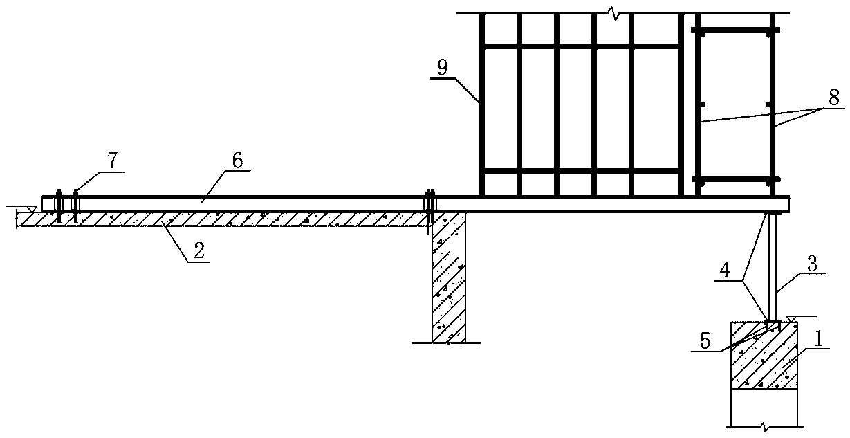
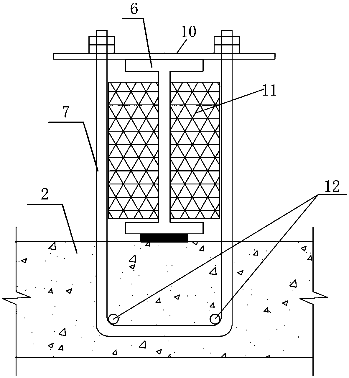
The invention discloses a large-span suspended member construction system and a construction method thereof. The construction system comprises a foundation pit supporting crown beam, a structural floor slab, a profile steel foundation, a round steel pipe, a template bracket and an outer scaffold. The foundation pit supporting crown beam is a reinforced concrete continuous beam. The arranging position of the structural floor slab is higher than the foundation pit supporting crown beam. A U-shaped connecting device is pre-buried in the structural floor slab; the first end part of the profile steel foundation is connected to the structural floor slab through the U-shaped connecting device. The lower end of the round steel pipe is fixedly connected to the foundation pit supporting crown beam,and the upper end of the round steel pipe is connected to a second end part of the profile steel foundation. The template bracket is arranged on the profile steel foundation. The outer scaffold is arranged on the profile steel foundation and the outer scaffold and the template bracket are arranged in a spaced manner. The scheme solves the problem that it is hard to construct a supporting rack bodyand the outer scaffold of a large-span suspended member at the same time effectively, it is ensured that the large-span suspended member is formed primarily, facilitates insertion of follow-up stepsin advance favorably and shortens the integral construction period.

Description

technical field [0001] The invention belongs to the technical field of large-span cantilever component construction, and in particular relates to a large-span cantilever component construction system and a construction method thereof. Background technique [0002] Cantilevered building components refer to an architectural effect achieved by building components using cable structures or other structures. Cantilever structure is one of the common structural forms in engineering structures, such as awnings, overhanging eaves, external balconies, overhanging corridors, etc. in construction projects. This structure is a beam or plate cantilevered from the main structure to form a cantilever structure. It is still a beam-slab structure in essence. With the rapid development of technology, in contemporary architecture, the scale of cantilever is getting bigger and bigger, and there are more and more ways of application, and it is also playing an increasingly important role in the ...

Claims


Application Information

Patent Timeline
IPC IPC(8): E04G3/18E04G5/04E04G13/06
CPCE04G3/18E04G5/04E04G5/045E04G13/066
Inventor 王龙张鹏李靖王振宇马瑞强樊芋
Owner 中国建筑土木建设有限公司
Learn More