
Piston pump with first opening and first closing sealing structure

A sealing structure, piston pump technology, applied in pump components, variable volume pump components, liquid variable volume machinery, etc., can solve the problems of efficiency loss, restricting the efficiency of high-speed operation of the piston pump, and inability to enter immediately, to prevent EFFECT OF EFFICIENCY LOSS

Pending Publication Date: 2020-06-26
东莞力嘉塑料制品有限公司
View PDF0 Cites 0 Cited by
  • Summary
  • Abstract
  • Description
  • Claims
  • Application Information

AI Technical Summary

Problems solved by technology

[0003] However, due to the material of the one-way valve of elastic material, its deformation has obvious hysteresis, that is, at the last moment when the piston pump completes the operation of inhaling the medium, the one-way valve of the suction port is in an open state; The one-way valve is in the closed state; the piston will immediately enter the process of discharging the medium under the action of the drive rod, but because the closing and opening of the one-way valve is completed by its own deformation, the one-way valve of the suction port changes from open to It takes time to complete the transition from closing to opening of the one-way valve of the discharge port, and it cannot enter the corresponding state immediately. This is the hysteresis of the one-way valve. Due to the existence of such a hysteresis, the piston pump never When the suction state enters the discharge state, the one-way valve at the suction port is still open for a short period of time, and the one-way valve at the discharge port is still closed, that is, when the piston compresses the medium, a part of the medium will flow along the suction port. It also flows into the outside of the suction end, resulting in efficiency loss. Such efficiency loss will be more obvious when the driving speed of the piston driving rod is faster, thus restricting the efficiency of the high-speed operation of the piston pump.

Method used


Image

  • Piston pump with first opening and first closing sealing structure
  • Piston pump with first opening and first closing sealing structure
  • Piston pump with first opening and first closing sealing structure

Examples


Embodiment 2

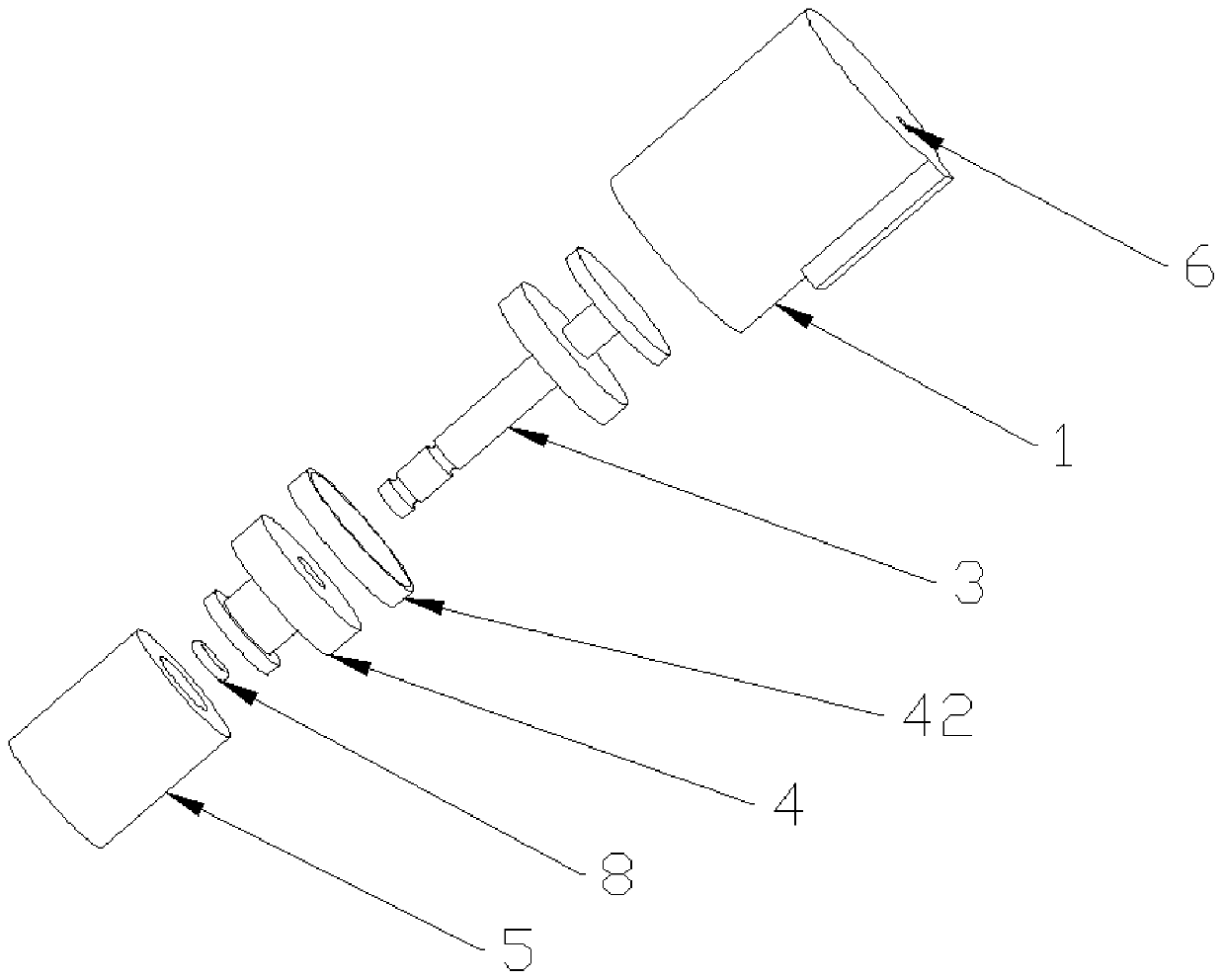
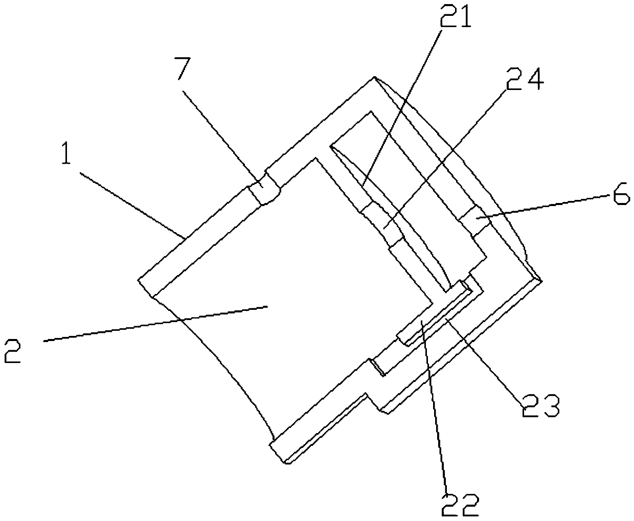
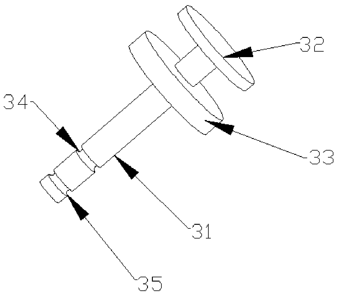
[0056] Embodiment two: if Figure 10 and Figure 11 As shown, the difference of this embodiment is that an elastic component 9 is arranged on the driving member, and the process of its air intake and exhaust is the same as that of the first embodiment. Specifically, a piercing groove 52 for the sealing rod 31 to penetrate is provided in the middle of the driving member 5, spring grooves 55 are symmetrically arranged on both side walls of the piercing groove 52, and the elastic assembly 9 includes a spring 91 arranged in the spring groove 55. , The end of the spring 91 is provided with a ball 92 . When the sealing rod 31 of the drive member 5 is moving, the ball 92 first abuts against the first locking position 34, and when the first sealing block 32 abuts against the partition plate 21, the movement of the entire sealing assembly 3 is restricted. When the driving member 5 continues to move downward, the spring 91 is squeezed by the spheroid 92, and the spheroid 92 is disenga...


PUM


Abstract

The invention discloses a piston pump with a first opening and first closing sealing structure. The piston pump comprises a piston barrel shell, wherein a cavity is formed in the piston barrel shell,a sealing assembly and a piston assembly are arranged in the cavity, a driving piece is further arranged in the cavity, the driving part can drive the sealing assembly to move to the limiting positionfirst, and then drive the piston assembly to move. According to the piston pump, the obvious hysteresis of the deformation due to a material of a check valve made of an elastic material is overcome,so that before suction operation by the piston pump, a suction inlet is in an open state, and an exhaust outlet is in a closed state; and before exhaust operation by the piston pump, the suction inletis in a closed state and the exhaust outlet is in an open state. The efficiency loss of the piston pump due to the hysteresis of the check valve is reduced or even eliminated so that the piston pumpcan run at a higher speed.

Description

technical field [0001] The invention relates to a piston pump, in particular to a piston pump with a first-open first-close sealing structure. Background technique [0002] The structure of a traditional piston pump includes: a piston driving rod, a piston, and a piston cylinder. The piston cylinder is provided with a suction port and a discharge port, and a valve structure is provided at the suction port and discharge port of the piston cylinder. During the process, the channel of the suction port is in an open state, and the channel of the discharge port is in a closed state; in the process of discharging the medium of the piston pump, the channel of the discharge port is in an open state, and the channel of the suction port is in a closed state; in this way, the suction can be completed media manipulation. The valve structure of the suction port and the discharge port of the existing piston pump is generally a one-way valve of elastic material, and its working principle ...

Claims


Application Information

Patent Timeline
Patent Type & Authority Applications(China)
IPC IPC(8): F04B39/12F04B39/00
CPCF04B39/0005F04B39/0022F04B39/122
Inventor 高龙叶德全韩超陈海笙陈汉雄
Owner 东莞力嘉塑料制品有限公司
Learn More