Heat accumulating type based incineration integrated equipment capable of circularly treating waste gas

A cyclic treatment, regenerative technology, applied in lighting and heating equipment, incinerators, combustion methods, etc., can solve the problems of increasing equipment cost, complex structure, low incineration efficiency, etc., to achieve convenient maintenance, improve anti-clogging ability, low-cost effects

Inactive Publication Date: 2020-06-26
嵊州市星丰环保节能设备厂
View PDF11 Cites 1 Cited by
  • Summary
  • Abstract
  • Description
  • Claims
  • Application Information

AI Technical Summary

Problems solved by technology

[0005] In order to solve the above technical problems, the present invention provides an integrated incineration equipment based on heat storage and recyclable waste gas treatment to solve the existing problem that the existing device cannot realize the uniform feeding of garbage, that is, evenly sprinkled On the incineration rack, the incineration efficiency is low, and the carbon ash after incineration on the incineration rack cannot be cleaned automatically, which also affects the incineration efficiency; moreover, most of the existing devices use a spiral propulsion structure for solid-liquid separation of garbage To implement, the structure is complex and the cost of equipment is increased

Method used


Image

  • Heat accumulating type based incineration integrated equipment capable of circularly treating waste gas
  • Heat accumulating type based incineration integrated equipment capable of circularly treating waste gas
  • Heat accumulating type based incineration integrated equipment capable of circularly treating waste gas

Examples


Embodiment

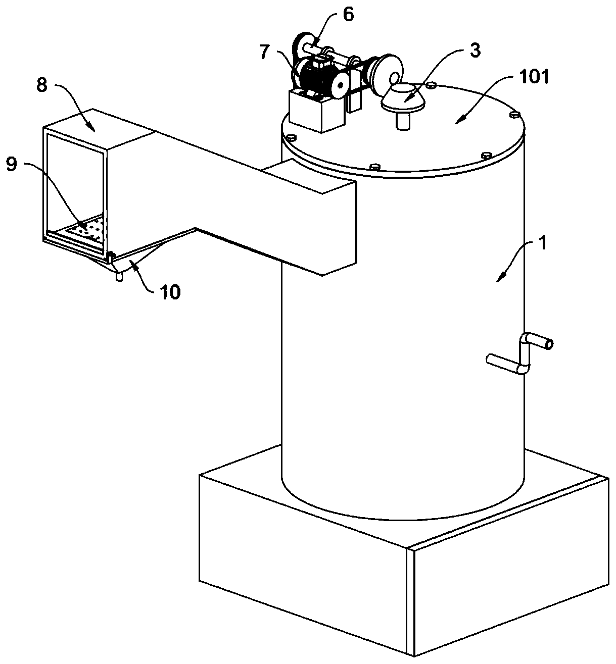
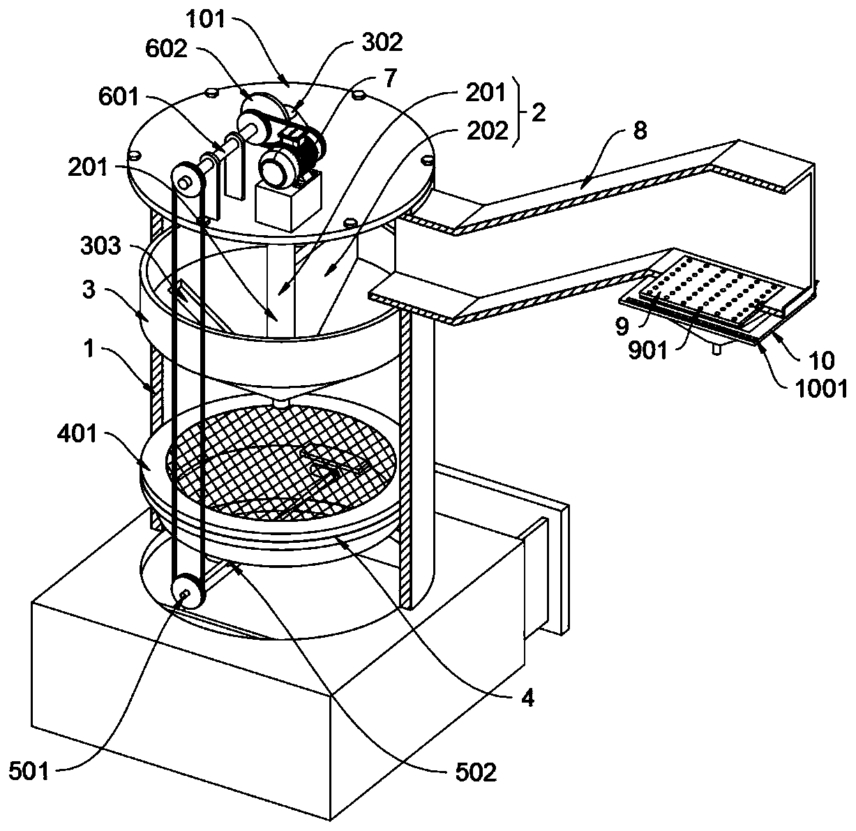
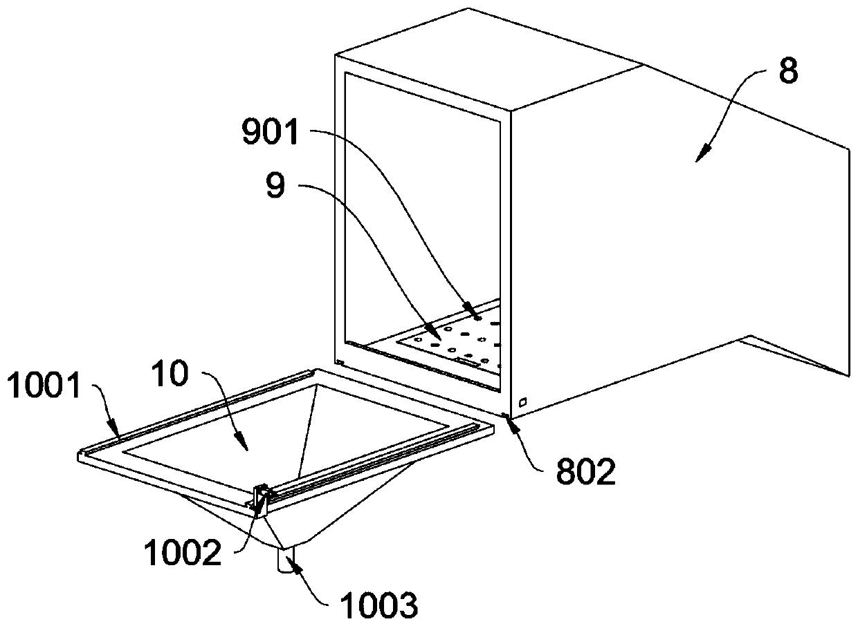
[0031] as attached figure 1 To attach Figure 8 Shown:

[0032] The present invention provides an integrated incineration equipment based on thermal storage and recyclable waste gas treatment, which includes an incineration bucket 1; A retaining ring 4 is welded inside the barrel 1; a vibration structure 5 is rotatably connected to the incineration barrel 1, and a transmission structure 6 is rotatably connected to the incineration barrel 1, and a servo motor 7 is fixedly connected to the incineration barrel 1 by bolts; refer to for example Figure 7 , the retaining ring 4 includes an incineration frame 401, the retaining ring 4 is a circular structure, and the incineration frame 401 is sleeved in the retaining ring 4, and the incineration frame 401 is provided with a supporting net; the vibration structure 5 includes a rotating shaft A501 and a dial Block 502, the rotating shaft A501 is connected to the incineration bucket 1 in rotation, and two toggle blocks 502 are symmetr...


PUM


Abstract

The invention provides heat accumulating type based incineration integrated equipment capable of circularly treating waste gas, relates to the field of incineration devices, and solves the problems that the existing device cannot be uniformly scattered on an incineration rack, so that the incineration efficiency is lower, and the incinerated carbon dust on the incineration rack cannot be automatically cleaned to also affect the incineration efficiency. The incineration integrated equipment comprises an incineration barrel, wherein a poking structure is welded to the incineration barrel; a servo motor drives a temporary collecting hopper to rotate and also drives a vibrating structure to rotate; when a rotary shaft A rotates by 60 degrees, two poking blocks are in contact with the bottom end face of the incineration rack; and the rotary shaft A and the poking blocks jointly form the vibrating type structure of the incineration rack, so that carbon dust is prevented from being accumulated on the incineration rack, and the incineration efficiency is further improved; and in addition, the temporary collecting hopper and the vibrating structure mutually form a linkage type structure, sothat vibrating deashing of the incineration rack can be realized while rotating to scatter the feedstock.

Description

technical field [0001] The invention belongs to the technical field of incineration devices, and more specifically relates to an integrated incineration equipment based on heat storage and recyclable waste gas treatment. Background technique [0002] Waste incineration is the most widely used waste treatment method in waste treatment. Waste incineration is to put waste into an incinerator for combustion, release heat energy, preheat for recycling, and then heat or generate electricity. [0003] Based on the above, the existing regenerative integrated waste gas incineration equipment currently has shortcomings in feeding and incineration efficiency: one is that the existing device cannot achieve uniform feeding of garbage, that is, uniform scattering On the incineration rack, the incineration efficiency is low, and the carbon ash after incineration on the incineration rack cannot be cleaned automatically, which also affects the incineration efficiency; moreover, most of the e...

Claims


Application Information

Patent Timeline
IPC IPC(8): F23G5/04F23G5/28F23G5/44F23J1/06
CPCF23G5/04F23G5/28F23G5/44F23G5/444F23J1/06
Inventor 姚帅锋陈鑫淑
Owner 嵊州市星丰环保节能设备厂
Why Eureka
Try Eureka