The belt pressure sensor of the belt feeding mechanism of the plate-shaped workpiece hemming device

A wrapping device and workpiece technology, applied in the direction of electromagnetic measuring devices, electrical components, electric/magnetic solid deformation measurement, etc., can solve the problems of manual wrapping operation of leaks, poor consistency of wrapping state, and bulkiness, etc., to overcome manual The effect of unreliable operation, easy mass production, and high degree of systematization

Active Publication Date: 2021-08-17
BEIBU GULF UNIV
View PDF10 Cites 0 Cited by
  • Summary
  • Abstract
  • Description
  • Claims
  • Application Information

AI Technical Summary

Problems solved by technology

[0003] In order to solve the difficulties such as poor consistency of wrapping state, deficiencies such as deviation, folds, and leaks, and cumbersome manual wrapping operation, the present invention provides a belt pressure sensor for the feeding belt mechanism of the edge wrapping device for plate-shaped workpieces. Piezoelectric sheet, right piezoelectric sheet composition

Method used


Image

  • The belt pressure sensor of the belt feeding mechanism of the plate-shaped workpiece hemming device
  • The belt pressure sensor of the belt feeding mechanism of the plate-shaped workpiece hemming device
  • The belt pressure sensor of the belt feeding mechanism of the plate-shaped workpiece hemming device

Examples


Embodiment Construction

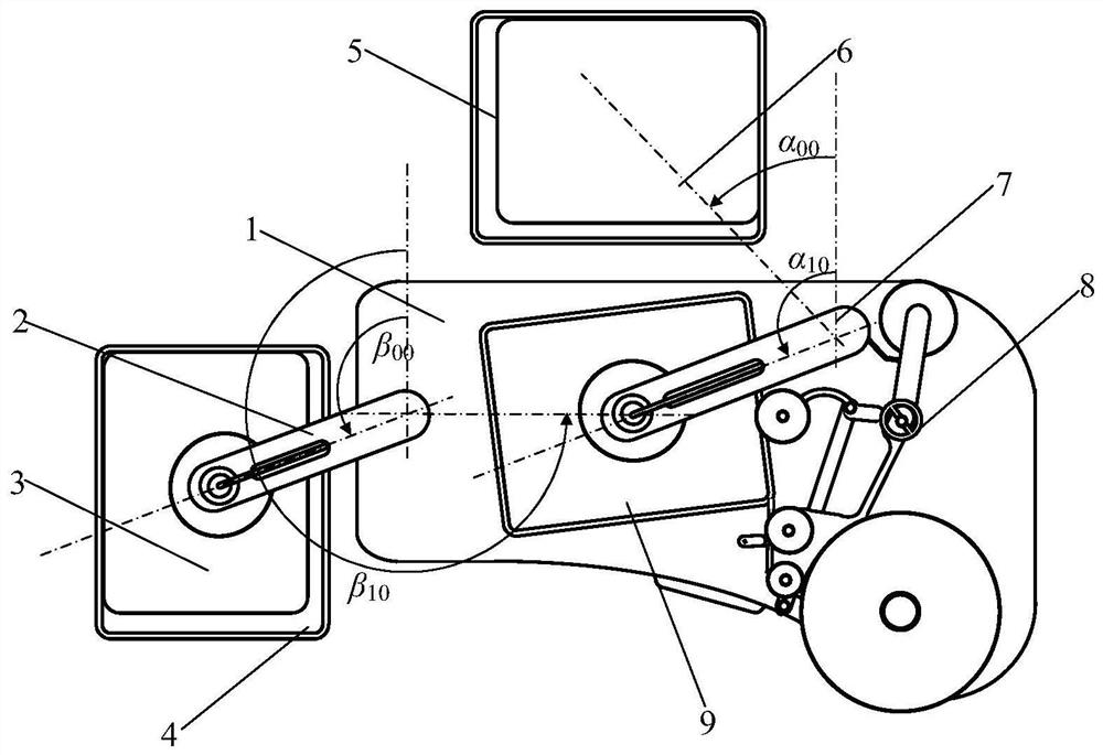
[0029] exist figure 1 One embodiment of the present invention shown—a plan view schematic diagram of a plate-shaped workpiece hemming method: the base 1, as the main workbench, chassis body and working and bearing surface of the overall system device, is located in the middle right of the workplace. The unloading mechanism 2 is used as a system device for grasping, transferring and lowering the package, and is assembled on the left end above the abutment 1 . The packaged piece 3 is the work object of the system device—the workpiece that has been hemmed is grasped, transferred, and lowered by the unloading mechanism 2, and placed in the unloading car 4 in turn. The unloading vehicle 4 is used as a transfer device for carrying and transporting the finished package 3, and is suspended on the left side of the base 1, at a positioning position to be loaded. The loading vehicle 5 is used as a transfer device for carrying and transporting the packaged items 6, and is suspended on th...


PUM


Abstract

The utility model relates to a belt pressure sensor of a feeding belt mechanism of a plate-shaped workpiece hemming device, which is composed of an elastic arm, a left piezoelectric sheet, and a right piezoelectric sheet. The head end of the spring arm is assembled on the tail end of the rocker arm through the adjustable elastic shaft structure of the adjustment handle. The left piezoelectric sheet is used as the pressure-convex left convex deformation sensing device of the elastic arm, which is made of variable resistance strain gauge, and is tightly attached to the left side of the elastic arm with special glue for strain gauges. The right piezoelectric sheet is used as the right concave deformation sensing device of the elastic arm, which is made of variable resistance strain gauge, and is tightly attached to the right side of the elastic arm with special glue for the strain gauge. One of the two lead wires of the left piezoelectric sheet is connected to one of the two lead wires of the right piezoelectric sheet, and the other lead wires of the left piezoelectric sheet and the right piezoelectric sheet are respectively connected to two pressure signal lines.

Description

technical field [0001] The invention relates to a method for wrapping the side of a flat workpiece. Background technique [0002] In many production lines of flat-shaped products, there is a process of side-wrapping flat-shaped workpieces, especially for circuit board manufacturers. This type of production process is: wrapping the entire periphery of the flat-shaped workpiece with a special adhesive tape. At present, this kind of process is all done manually, and the result is that the consistency of the wrapping state is poor, and there are defects such as partial sticking, folds, and leaks in different parts. For the usual large and heavy boards, manual operation is more difficult. This is a bottleneck that seriously affects the process of related product production lines, hindering the automation of the entire production process. Therefore, it is urgent to develop an automatic method that can ensure the consistency of the wrapping state and replace the heavy manual ope...

Claims


Application Information

Patent Timeline
Patent Type & Authority Patents(China)
IPC IPC(8): G01B7/16H05K3/00
CPCG01B7/18H05K3/00
Inventor 屈百达赵荣阳梁家海程宪宝韩开旭
Owner BEIBU GULF UNIV
Why Eureka
Try Eureka