Airtightness detection system of pressure vessel

A technology for air tightness detection and pressure vessels, which is applied in the direction of using liquid/vacuum degree for liquid tightness measurement and detecting the appearance of fluid at the leakage point, etc. It can solve improper sealing at the interface, complex clamping tool structure, Inconvenient use and maintenance, etc., to achieve the effect of low cost, good sealing effect and convenient operation

Inactive Publication Date: 2020-06-26
张康乐
View PDF13 Cites 6 Cited by
  • Summary
  • Abstract
  • Description
  • Claims
  • Application Information

AI Technical Summary

Problems solved by technology

[0003] However, the following problems exist in the air tightness testing of existing pressure vessels. a. Most of the methods adopted at the present stage are to pass gas into the inside of the pressure vessel for testing, but this method is often improperly sealed at the interface. Leaked gas will affect the judgment of the testing personnel, often leading to inaccurate testing results and affecting the use of pressure vessels; b, when the existing pressure vessel is tested for air tightness, the structure of the clamping tool at the interface of the pressure vessel is complicated, and the use of It is inconvenient to maintain and maintain, which reduces the efficiency of detection. It can be applied to the detection of large quantities of pressure vessels. While ensuring the detection effect, it is easy to operate, low in cost, and reduces the labor load of employees.

Method used


Image

  • Airtightness detection system of pressure vessel
  • Airtightness detection system of pressure vessel
  • Airtightness detection system of pressure vessel

Examples


Embodiment Construction

[0023] The embodiments of the present invention will be described in detail below with reference to the accompanying drawings, but the present invention can be implemented in many different ways defined and covered by the claims.

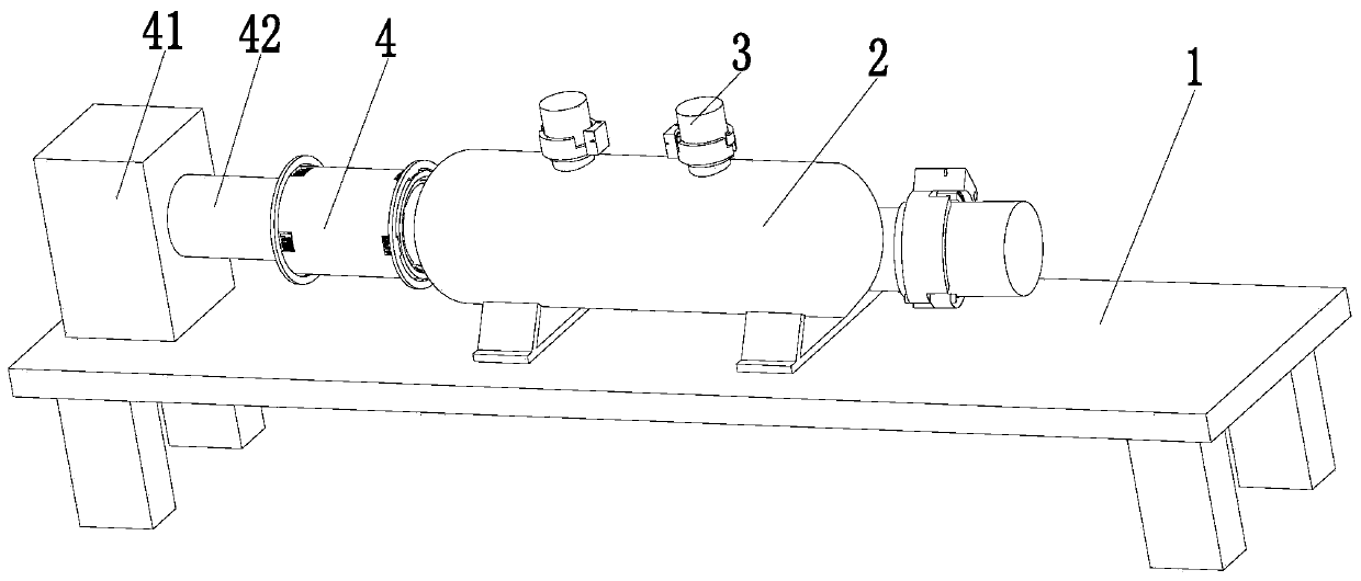
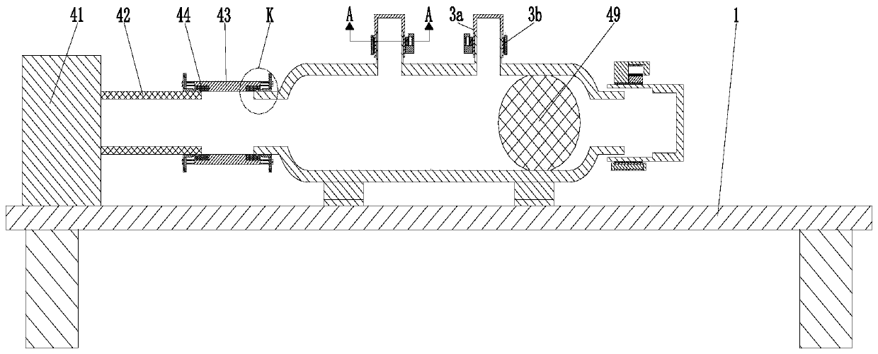
[0024] Such as Figure 1 to Figure 6 As shown, a pressure vessel airtightness detection system includes a test platform 1, a pressure vessel body 2, a sealing device 3 and a gas delivery device 4. The pressure vessel body 2 is placed on the test platform 1, and the test platform 1 A gas delivery device 4 is provided, and a sealing device 3 is connected to the upper end of the pressure vessel body 2 .

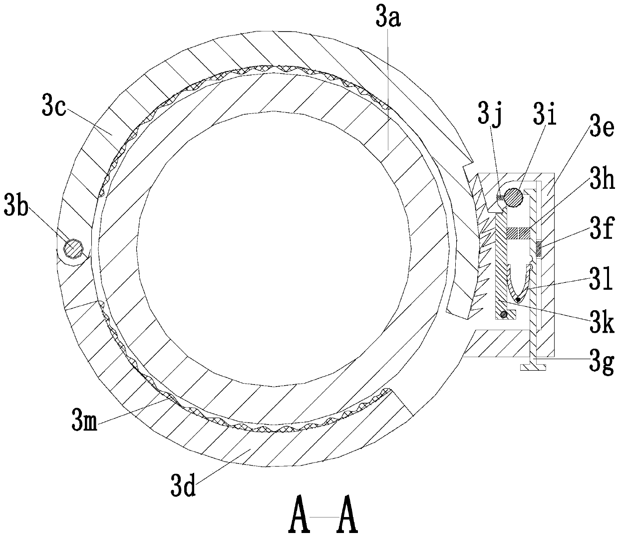
[0025] The sealing device 3 includes a sealing tube 3a, a connecting rod 3b, a locking half ring 3c, an unlocking half ring 3d, a locking plate 3e, a slider 3f, a positioning rod 3g, a top block 3h, a rotating rod 3i, Push rod 3j, locking rod 3k, U-shaped shrapnel 3l and rubber plate 3m, the sealing pipe 3a is sleeved on the air inlet at the upper en...


PUM


Abstract

The invention relates to an air tightness detection system for a pressure vessel. The system comprises a test platform, a pressure vessel body, a sealing device and a gas transmission device, and thepressure vessel body is placed on the test platform. The gas transmission device is arranged on the test platform; the upper end of the pressure vessel body is connected with the sealing device. According to the invention, the following problems existing in air tightness detection of a conventional pressure vessel can be solved: a, gas is introduced into a pressure container for detection in mostmethods adopted at the present stage, but often inaccurate detection results exist due to the fact that the leaked gas affects the judgment of detection personnel due to improper sealing treatment ata joint; and b, when the air tightness of the existing pressure vessel is detected, a clamping tool at the interface of the pressure vessel is complex in structure and inconvenient to use and maintain. The air tightness detection system can be suitable for detecting a large batch of pressure vessels, the detection effect can be ensured, and the labor amount of staff is reduced.

Description

technical field [0001] The invention relates to the technical field of pressure vessel manufacturing, in particular to a pressure vessel airtightness detection system. Background technique [0002] A pressure vessel is a closed vessel that can withstand pressure. The pressure vessel has a wide range of uses. It has an important position and role in many sectors such as industry, civil, military, and many fields of scientific research. Because pressure vessels are generally relatively large It is used under high pressure, which has certain safety hazards. During the production of pressure vessels, each pressure vessel needs to be tested for air leakage, especially the detection of the weld of the pressure vessel is an important part. [0003] However, the following problems exist in the air tightness testing of existing pressure vessels. a. Most of the methods adopted at the present stage are to pass gas into the inside of the pressure vessel for testing, but this method is o...

Claims


Application Information

Patent Timeline
Patent Type & Authority Applications(China)
IPC IPC(8): G01M3/04
CPCG01M3/04
Inventor 张康乐张金峰
Owner 张康乐
Why Eureka
Try Eureka