
A kind of heat dissipation device for multifunctional power equipment and using method thereof

A technology for power equipment and heat sinks, which is applied to the cooling/ventilation of substations/switchgears, and the boards/panels/desks of substations/switchgears. and other problems, to avoid the confusion of wiring, avoid confusion, and facilitate maintenance.

Active Publication Date: 2021-05-18
北民电气科技有限公司
View PDF14 Cites 0 Cited by
  • Summary
  • Abstract
  • Description
  • Claims
  • Application Information

AI Technical Summary

Problems solved by technology

[0004] The purpose of the present invention is to solve the problems in the prior art that the bottom of the power element is in close contact with the upper end of the supporting plate, the heat dissipation effect is poor, and the internal wiring of the box-type substation is chaotic, and it is difficult to carry out maintenance work. The heat dissipation device for equipment and its use method can not only dissipate heat from the bottom of the power components, avoid circuit breakage or disconnection caused by excessive temperature at the bottom, ensure the normal operation of the box-type substation, but also sort out the lines to avoid walking Wire tangles are messy and easy to access in the event of a circuit failure

Method used


Image

  • A kind of heat dissipation device for multifunctional power equipment and using method thereof
  • A kind of heat dissipation device for multifunctional power equipment and using method thereof
  • A kind of heat dissipation device for multifunctional power equipment and using method thereof

Examples


Embodiment Construction

[0029] The following will clearly and completely describe the technical solutions in the embodiments of the present invention with reference to the accompanying drawings in the embodiments of the present invention. Obviously, the described embodiments are only some, not all, embodiments of the present invention.

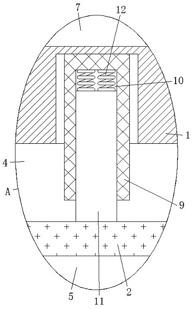
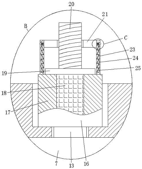
[0030] refer to Figure 1-4 , a heat dissipation device for multifunctional power equipment, comprising a mounting plate 1, the power element is fixedly connected to the upper end of the mounting plate 1 through a threaded rod, the mounting plate 1 is provided with a heat dissipation mechanism, and the heat dissipation mechanism includes a mounting plate set on the mounting plate 1 Slot, the magnetic plate 2 is slidingly connected in the installation groove, and the horizontal plate 3 is fixedly connected in the installation groove. The magnetic plate 2 and the horizontal plate 3 divide the installation groove into the first chamber 4, the second chamber 5, and the th...


PUM


Abstract

The invention discloses a heat dissipation device for multifunctional power equipment, which comprises a mounting plate, a heat dissipation mechanism is arranged on the mounting plate, and two heat conduction pipes extending into and fixedly connected with the heat dissipation mechanism are symmetrically embedded on the mounting plate. The mounting plate is symmetrically provided with two connecting mechanisms extending above it, and the cooling mechanism includes a mounting slot opened on the mounting plate, and a magnetic plate is slidably connected in the mounting slot. A horizontal plate is fixedly connected, and the magnetic plate and the horizontal plate divide the installation slot into a first chamber, a second chamber and a third chamber. The invention has a reasonable structure design, which can not only dissipate heat from the bottom of the power element, avoid circuit breakage or circuit breakage due to excessively high bottom temperature, and ensure the normal operation of the box-type substation, but also can sort out the lines and avoid wiring confusion. And when the circuit fails, it is easy to repair it.

Description

technical field [0001] The invention relates to the technical field of heat dissipation for electric equipment, in particular to a heat dissipation device for multifunctional electric equipment and a method for using the same. Background technique [0002] Box-type substation, also known as prefabricated substation or prefabricated substation, organically combines high-voltage power receiving, transformer step-down, low-voltage power distribution and other functions, and is installed in a moisture-proof, rust-proof, dust-proof, isolated The steel structure box with heat and other functions is integrated with mechatronics and fully enclosed. It is especially suitable for urban network construction and transformation. It is a brand-new substation that has emerged after the civil substation. [0003] At present, during the operation of the box-type substation, the power components are mostly fixed on the supporting plate in the box-type substation. Since the bottom of the power...

Claims


Application Information

Patent Timeline
Patent Type & Authority Patents(China)
IPC IPC(8): H02B1/56H02B1/04
CPCH02B1/04H02B1/56
Inventor 段瑞霞
Owner 北民电气科技有限公司
Learn More