Differential amplifier common-mode rejection ratio and gain trimming circuit
A technology of differential amplifier and common mode rejection ratio, which is applied in the electronic field, can solve the problems of increasing the cost of test and adjustment time, increasing the cost of the circuit, etc., and achieve the effect of reducing the cost of test and adjustment, low circuit cost and reducing the cost of the circuit
- Summary
- Abstract
- Description
- Claims
- Application Information
AI Technical Summary
Problems solved by technology
Method used
Image
Examples
Embodiment 1
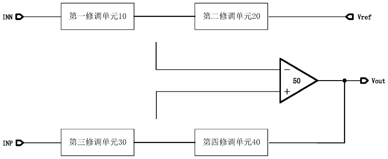
[0040] This embodiment discloses a differential amplifier common-mode rejection ratio and gain trimming circuit, image 3A schematic diagram of the common-mode rejection ratio and gain trimming circuit of the differential amplifier in this embodiment is shown. The trimming circuit includes: a first trimming unit 10 and a second trimming unit 20 connected between the non-inverting input voltage INP and a reference voltage Vref, the first trimming unit 10 and the second trimming unit 20 The positive input terminal of the differential amplifier 50 is connected by means of a tap switch; the third trimming unit 30 and the fourth trimming unit 40 connected between the inverting input voltage INN and the output terminal Vout of the differential amplifier 50, said The third trimming unit 30 and the fourth trimming unit 40 are connected to the negative input end of the differential amplifier 50 through a tap switch. The gain can be fine-tuned by changing the tap positions of the first...
Embodiment 2
[0057] The trimming circuit in this embodiment is basically the same as the trimming circuit in Embodiment 1. The difference is that in this embodiment, the second trimming resistor strings R4a, R4b, R5a, and R5b respectively include 2 m unit resistance, therefore, the trimming bit in this embodiment is m+1bit.
Embodiment 3
[0059] The trimming circuit in this embodiment is basically the same as the trimming circuit in Embodiment 1, the difference is that in this embodiment, the second trimming auxiliary trimming resistor string R8a, R8b, R9a, R9b includes 2 parallel-connected n unit resistance. The first trimming resistor string R3a, R3b, R5a, R5b includes 2 n -1 unit resistance. In this example, the minimum resistance is Different minimum resistor values can be used as desired.
PUM
 Abstract
Description
Claims
Application Information
 - R&D
- Intellectual Property
- Life Sciences
- Materials
- Tech Scout
- Unparalleled Data Quality
- Higher Quality Content
- 60% Fewer Hallucinations
Browse by: Latest US Patents, China's latest patents, Technical Efficacy Thesaurus, Application Domain, Technology Topic, Popular Technical Reports.
© 2025 PatSnap. All rights reserved.Legal|Privacy policy|Modern Slavery Act Transparency Statement|Sitemap|About US| Contact US: help@patsnap.com


