Forming method of incremental thickening of flange at any position of pipe

A technology for flanges and pipes, which is applied in the field of progressively thickening and forming flanges at any position in the axial direction of pipes. It can solve the problems of increasing deformation and achieve the effects of preventing distortion or filling dissatisfaction, expanding the applicable range of the process, and improving the forming limit.

Active Publication Date: 2021-05-07
SHANGHAI JIAOTONG UNIV
View PDF6 Cites 0 Cited by
  • Summary
  • Abstract
  • Description
  • Claims
  • Application Information

AI Technical Summary

Problems solved by technology

[0003] Aiming at the above-mentioned deficiencies in the prior art, the present invention proposes a method for progressively thickening the flange at any position of the pipe, and increases the amount of deformation by controlling the deformation zone to meet the demand for thickening the flange at any position

Method used


Image

  • Forming method of incremental thickening of flange at any position of pipe
  • Forming method of incremental thickening of flange at any position of pipe
  • Forming method of incremental thickening of flange at any position of pipe

Examples


Embodiment 1

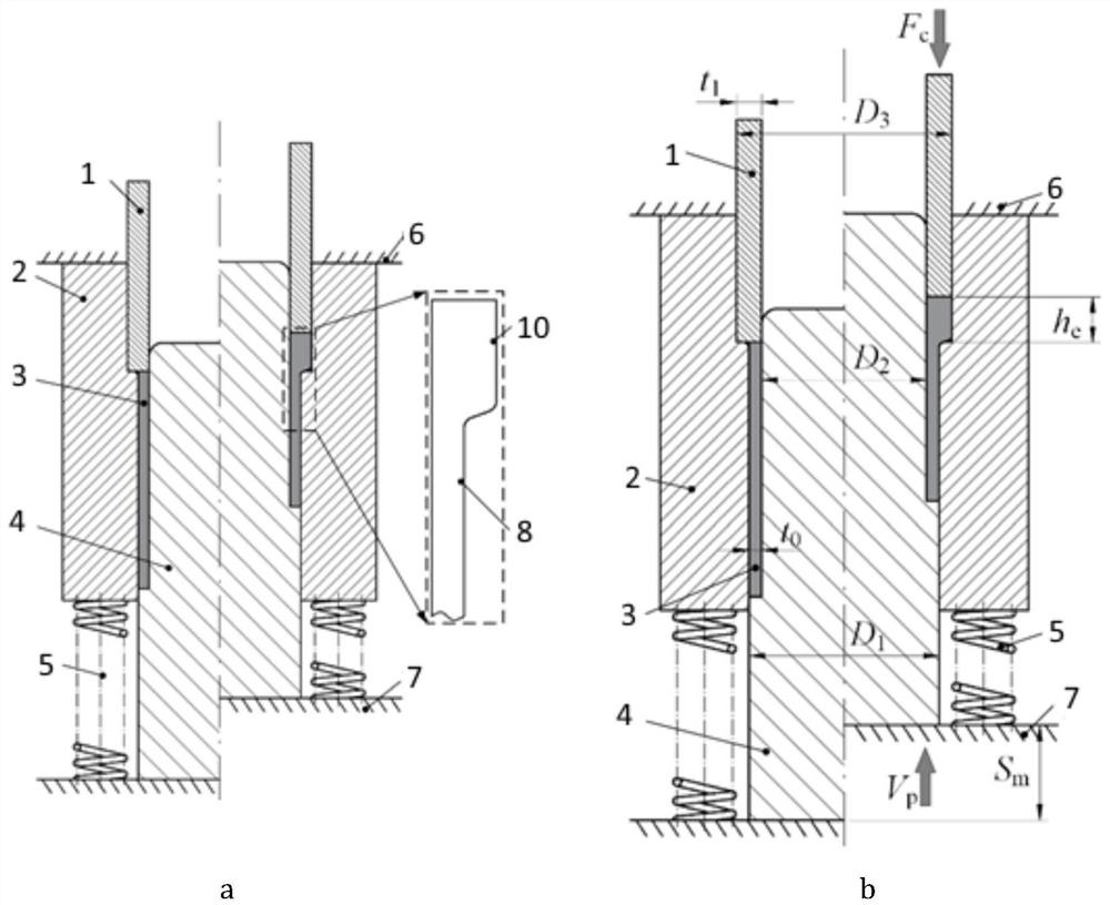
[0024] Such as figure 1 , image 3 with Figure 4 As shown, in this embodiment, the flange thickening is formed at the end of the pipe fitting 3, and the specific position is the upper nozzle h of the pipe fitting 3 e Section, specifically provide constant pressure F through external hydraulic equipment c , and use the compression molding device with workbench 6, 7 to carry out upsetting processing on the pipe fitting 3, and set the stroke S of the workbench according to the size of the flange to be formed m , so that the table moves at a constant speed V p Drive the compression molding device, as the mandrel 4 goes up, the pipe fitting 3 is gradually squeezed into the forming cavity from the positioning cavity, and the side wall of the pipe fitting 3 is gradually thickened until the stroke ends to form a flange.

[0025] The compression molding device includes: a reverse top punch 1, a die 2 and a mandrel 4, wherein: the reverse top punch 1 is slidably matched with the di...

Embodiment 2

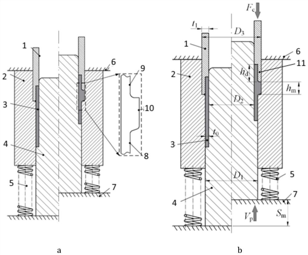
[0034] Such as figure 2 , image 3 with Figure 4 As shown, in this embodiment, the flange thickening is formed in the middle of the pipe fitting 3, and the specific thickening position is h from the upper nozzle of the pipe fitting 3 d place. Compared with Embodiment 1, the reverse punch 1 of this embodiment has added a positioning structure 11, so the closed cavity where the pipe fittings are located can be divided into three parts. The specific conditions are as follows:

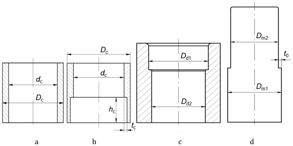
[0035] The reverse top punch 1 with the positioning structure is as image 3 As shown in b, the height of the positioning structure is h c and satisfy h c = h d , with a width of t c and satisfy t c = t 0 .

[0036] The closed cavity includes in turn: a forming cavity 10, a protective cavity 8 and a positioning cavity 9, wherein: the diameter of the forming cavity 10 is the same as the outer diameter of the flange, and the diameter of the protective cavity 8 is the same as the outer diameter of...


PUM


Abstract

A flange thickening method based on pipe material. By applying back pressure to the reverse punch and setting the mandrel to move upward at a constant speed, the pipe is subjected to upsetting processing. As the deformation force inside the pipe gradually increases, it will be located at The pipe fitting material protecting the cavity is gradually extruded into the forming cavity, and the side wall of the pipe fitting in the forming cavity is accumulated and thickened, and finally forms a flange. The invention makes the side wall materials gradually accumulate and form, which can effectively prevent defects such as distortion or insufficient filling of the pipe wall, and improves the forming limit and forming efficiency of flange thickening; by adding a positioning cavity in the punch, any part of the pipe wall can be realized The one-time forming of the flange expands the scope of application of the process.

Description

technical field [0001] The invention relates to a technique in the field of plastic forming of metal materials, in particular to a process method for progressively thickening and forming a flange at any position in the axial direction of a pipe. Background technique [0002] As an indispensable part in industrial production, pipes are widely used in metallurgy, chemical industry and automobile industry. In order to achieve special functions, pipes often have different wall thicknesses in the axial direction, and the most typical feature is the flange feature. For the flange features at the end, the upsetting method is often used. Due to the limitation of the height-to-diameter ratio of the upsetting part, the amount of upsetting deformation is small; for the flange features in the middle, the direct upsetting method is often used, and different molds are designed. The cavity achieves the purpose of thickening the pipe wall, but this type of forming method is limited by the ...

Claims


Application Information

Patent Timeline
Patent Type & Authority Patents(China)
IPC IPC(8): B21C23/02B21C25/02
CPCB21C23/02B21C25/02
Inventor 庄新村朱圣法朱印肖思雨赵震
Owner SHANGHAI JIAOTONG UNIV
Why Eureka
Try Eureka