
Structure used for eliminating reverse ejection action of lower pressing plate of progressive die

A technology of pressing plate and progressive die, applied in the field of mold manufacturing, can solve the problems of high force of the lower pressing plate, product wrinkle, reverse top, etc., to prevent the reverse top effect, apply uniform force, and delay the lifting time. Effect

Inactive Publication Date: 2020-06-30
天津世亚模具股份有限公司
View PDF0 Cites 0 Cited by
  • Summary
  • Abstract
  • Description
  • Claims
  • Application Information

AI Technical Summary

Problems solved by technology

[0003] When the progressive die is in the stretch forming station, due to the influence of the forming time and the difference in the mold opening time of the upper and lower molds, the punch and the clamping plate will rise at the same time when the upper and lower molds are closed and the mold is opened. There is a time difference in the rise of the male, and the force of the lower clamping plate is relatively large, and the rising speed of the lower clamping plate is greater than that of the upper clamping plate, which leads to the so-called reverse top phenomenon.
At this time, the upper pressing plate has not yet separated from the product, and the lower pressing plate will force the product up when it rises, causing serious wrinkles on the product

Method used


Image

  • Structure used for eliminating reverse ejection action of lower pressing plate of progressive die
  • Structure used for eliminating reverse ejection action of lower pressing plate of progressive die

Examples


Embodiment Construction

[0013] The present invention will be described in further detail below with reference to the accompanying drawings and through specific embodiments.

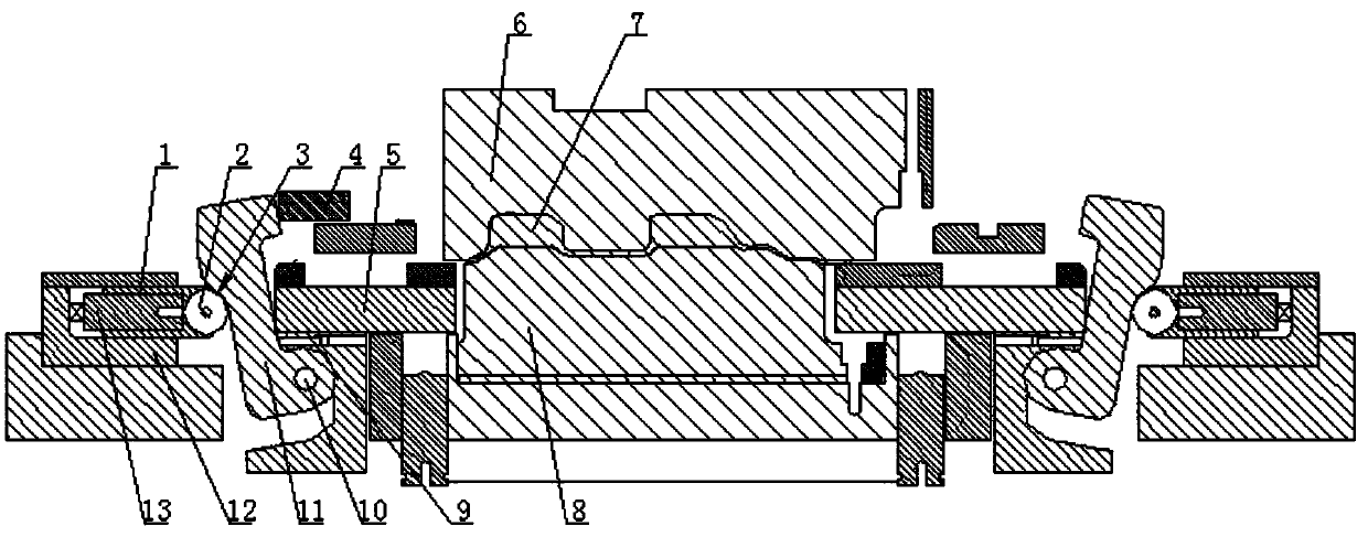
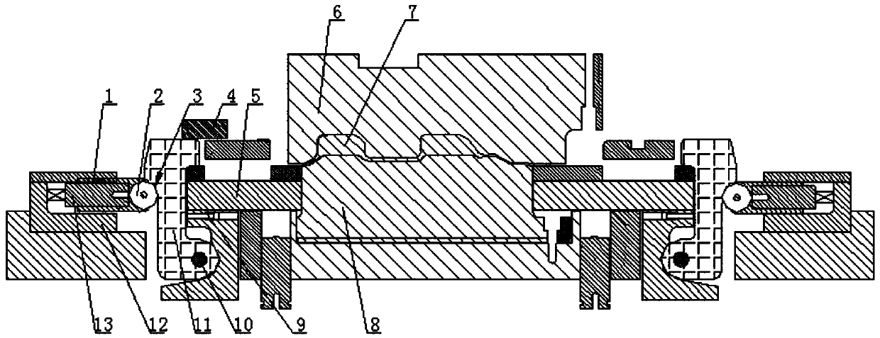
[0014] A structure for eliminating the reverse effect of the lower pressing plate of the progressive die, including an upper pressing plate 6 and a lower pressing plate 8. The innovation of the present invention is that a friction block is respectively installed on the opposite sides of the lower pressing plate. 5. The end faces of the two friction blocks facing away from the lower pressing plate are respectively connected with a feeding device. Tight crimp.

[0015] In this embodiment, the feeding device includes a pendulum block 11 and a slider 1, the pendulum block is installed in a pendulum block fixing seat 9, the pendulum block fixing seat is arranged on the side of the friction block, and is located in the pendulum block fixing seat The side of the seat facing away from the friction block is provided with a sliding block...


PUM


Abstract

The invention belongs to the field of die manufacture and particularly provides a structure used for eliminating the reverse ejection action of a lower pressing plate of a progressive die. The structure comprises an upper pressing plate and the lower pressing plate, wherein friction blocks are mounted on two opposite sides of the lower pressing plate respectively, a feeding device is connected with the end surface, opposite to the lower pressing plate, of each friction block, and the feeding device can drive the friction block on the same side to transversely reciprocate and realizes tight press connection of the friction block and the end surface of the lower pressing plate; each feeding device comprises a swing block and a slider, the swing block is mounted in a swing block fixing seat which is arranged on the side of the corresponding friction block, a slider fixing seat is arranged on one side, opposite to the friction block, of the swing block fixing seat, the slider is mounted inthe slider fixing seat, an opening is formed in the end part, located on the same side with the swing block, of the slider fixing seat, the slider extends out from the opening, and a nitrogen springis mounted at the end part, located in the slider fixing seat, of the slider.

Description

technical field [0001] The invention belongs to the field of mold manufacturing, in particular to a structure for eliminating the back-up effect of a presser plate under a progressive die. Background technique [0002] The progressive die is composed of multiple stations, each station completes different processing in sequence, and completes a series of different stamping processing in one stroke of the punch. After one stroke is completed, the punch feeder moves the material forward according to a fixed step, so that multiple processes can be completed on a set of molds, generally punching, blanking, bending, trimming, stretching. ,and many more. [0003] In the process of the progressive die in the stretching forming station, due to the influence of the molding time and the difference in the opening time of the upper and lower dies, the punch and the pressing plate will rise at the same time when the upper and lower dies are closed and opened. There is a time difference ...

Claims


Application Information

Patent Timeline
Patent Type & Authority Applications(China)
IPC IPC(8): B21D37/08
CPCB21D37/08
Inventor 林世大许立明赵青龙
Owner 天津世亚模具股份有限公司
Learn More