Unlock instant, AI-driven research and patent intelligence for your innovation.

Concrete mixer

A technology for concrete mixers and mixing barrels, applied in mixing plants, cement mixing devices, clay preparation devices, etc., can solve problems affecting the quality of concrete, insufficient mixing of raw materials, etc., and achieve the effect of fast discharging speed and high efficiency

Inactive Publication Date: 2020-06-30
刘长东
View PDF5 Cites 1 Cited by
  • Summary
  • Abstract
  • Description
  • Claims
  • Application Information

AI Technical Summary

Problems solved by technology

Most of the existing concrete mixers are composed of rotatable stirring rods in the mixing tank. The raw materials in the mixing tank are stirred by the rotation of the stirring rods. The axial force makes the raw materials prone to insufficient mixing and affects the quality of concrete

Method used


Image

  • Concrete mixer
  • Concrete mixer
  • Concrete mixer

Examples


specific Embodiment approach 1

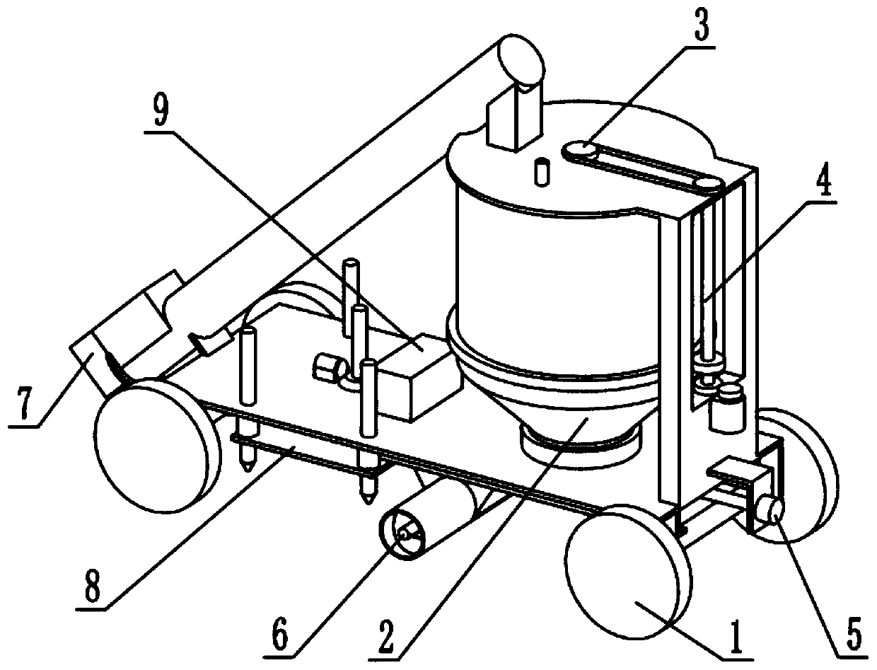
[0030] Such as Figure 1-12 As shown, a concrete mixer includes a support frame 1, a mixing bucket 2, a stirring rotor 3, a stirring transmission mechanism 4, a discharge control mechanism 5, a discharge conveying mechanism 6, a feed conveying mechanism 7, a device positioning mechanism 8 and The power supply 9, the mixing barrel 2 is rotatably connected to the support frame 1, the stirring rotating core 3 is rotatably connected to the supporting frame 1, the stirring rotating core 3 is located in the mixing barrel 2, and the stirring transmission mechanism 4 is connected to In the support frame 1, the stirring transmission mechanism 4 is connected to the mixing drum 2 and the stirring rotor 3, and the discharge control mechanism 5 is slidably connected to the lower end of the support frame 1, and the discharge control mechanism 5 is attached to the lower end of the mixing drum 2. Together, the discharge conveying mechanism 6 is rotatably connected in the discharge control mec...

specific Embodiment approach 2

[0033] Such as Figure 1-12 As shown, the support frame 1 includes a support base plate 1-1, a ring seat 1-2, a moving wheel 1-3, a support shaft 1-4, a mounting plate 1-5, a vertical plate 1-6, and a cover plate 1 -7, water inlet pipe 1-8, feed pipe 1-9, feed pipe 1-10, limit sleeve 1-11, mobile motor 1-12, feeding port 1-13, slideway plate 1-14 and fixed Pipe 1-15, the middle part of the support base plate 1-1 is fixedly connected with a ring seat 1-2, the front and rear ends of the support base plate 1-1 are connected with the support shaft 1-4 through bearing rotation, and the two support shafts 1-4 The two ends of each are fixedly connected with moving wheels 1-3, the vertical plate 1-6 is fixedly connected to the rear end of the support base plate 1-1, the mounting plate 1-5 is fixedly connected to the rear end of the vertical plate 1-6, and the cover plate 1 -7 is fixedly connected to the upper end of the vertical plate 1-6, and the cover plate 1-7 is provided with a w...

specific Embodiment approach 3

[0036] Such as Figure 1-12 As shown, the mixing barrel 2 includes an upper cylinder 2-1, a gear ring 2-2, a cone 2-3, a lower cylinder 2-4 and a stirring column 2-5, and the upper cylinder 2-1 is fixedly connected On the upper end of the cone 2-3, the lower cylinder 2-4 is fixedly connected to the lower end of the cone 2-3, the gear ring 2-2 is fixedly connected to the upper cylinder 2-1, and the upper cylinder 2-1 and the cone A plurality of stirring columns 2-5 are fixedly connected in the cylinder 2-3, the upper cylinder 2-1 is connected to the limit sleeve 1-11 through the bearing rotation, and the lower cylinder 2-4 is connected to the circular seat through the bearing rotation within 1-2;


PUM


Abstract

The invention relates to the field of construction equipment, in particular to a concrete mixer. The concrete mixer comprises a supporting rack, a stirring barrel, a stirring rotation core, a stirringtransmission mechanism, a discharging control mechanism, a discharging conveying mechanism, a feeding conveying mechanism, a device positioning mechanism and a power source. The stirring transmissionmechanism performs transmission on the stirring barrel and the stirring rotation core, so that the stirring barrel and the stirring rotation core rotate reversely, the concrete is stirred in the circumference direction and the axial direction, and thus the concrete can be sufficiently stirred. Through the discharging control mechanism and the discharging conveying mechanism, discharging of the concrete mixer is controlled, and the discharging efficiency is improved. Through the feeding conveying mechanism, a raw material can be added into the stirring barrel at the lower end of the concrete mixer, so that the raw material is more conveniently added. The concrete mixer remains and is fixed through the device positioning mechanism. According to the concrete mixer, the raw material can be sufficiently mixed, so that the quality of the concrete is prevented from being influenced.

Description

technical field [0001] The invention relates to the field of construction equipment, in particular to a concrete mixer. Background technique [0002] Concrete, referred to as "concrete", its birth can be traced back to ancient times. It is a commonly used building material, which is composed of sand, cementitious materials and mud. It needs to be stirred by mixing settings to make the concrete The ingredients are mixed evenly. Most of the existing concrete mixers are composed of rotatable stirring rods in the mixing tank. The raw materials in the mixing tank are stirred by the rotation of the stirring rods. The axial force makes the raw materials prone to insufficient mixing and affects the quality of concrete. Contents of the invention [0003] The purpose of the present invention is to provide a concrete mixer, which can fully mix raw materials and avoid affecting the quality of concrete. [0004] The purpose of the present invention is achieved through the following ...

Claims


Application Information

Patent Timeline
IPC IPC(8): B28C5/32B28C7/10B28C7/12B28C7/16B28C9/04
CPCB28C5/32B28C7/10B28C7/12B28C7/16B28C7/167B28C9/04
Inventor 刘长东
Owner 刘长东