A kind of coating equipment of automobile door handle
A technology for covering equipment and door handles, which is applied to household appliances, other household appliances, and household components, etc. It can solve the problems of difficult to guarantee the quality of the covering, occupying many hands, and cumbersome operations, etc., to achieve efficient and comprehensive covering operations , reduce the work load, facilitate the effect of unloading
- Summary
- Abstract
- Description
- Claims
- Application Information
AI Technical Summary
Problems solved by technology
Method used
Image
Examples
Embodiment 1
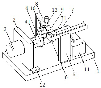
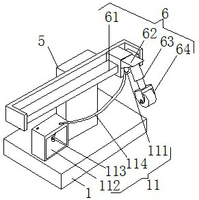
[0024]Embodiment 1: A coating device for a car door handle, including a bottom plate 1, a clamping mechanism 4, a coating fixture mechanism 6, an adjustment mechanism 7, a precise control baking mechanism 9, a cutting mechanism 10 and a maintenance mechanism 11, and the bottom plate 1 Provide support and installation place, the left side of the upper wall of the bottom plate 1 is provided with a vertical plate 2, the left wall of the vertical plate 2 is provided with a motor 3, the output shaft of the motor 3 is connected with the wall of the vertical plate 2 through bearings, and the motor 3 The output shaft of the vertical plate 2 extends to the right side of the vertical plate 2, and the motor 3 on the left wall of the vertical plate 2 runs, and then drives the clamped door handle to rotate and cover the operation. Connected, the clamping mechanism 4 is arranged on the right end of the output shaft of the motor 3, the cladding fixture mechanism 6 is arranged on the upper end...
Embodiment 2
[0027] The difference between this embodiment and Embodiment 1 is:
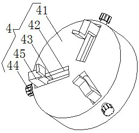
[0028] In this embodiment, the clamping mechanism 4 includes a rotating disk 41, a bar-shaped adjustment groove 42, a wire post 43, a knob 44, and a splint 45. The center of the left wall of the rotating disk 41 is fixedly connected to the right end of the output shaft of the motor 3. Two bar-shaped adjustment grooves 42 are equiangularly arranged on the right wall of the rotating disc 41, and the wire post 43 is rotatably connected with the inner wall of the bar-shaped adjustment groove 42 through a bearing, and the outer end of the wire post 43 extends to the bottom of the bar-shaped adjustment groove 42 The outside is provided with a knob 44 at the end, the support block at the left end of the splint 45 is threadedly connected with the wire column 43, the slider on the side wall of the support block at the left end of the splint 45 is slidingly connected with the inner wall chute of the bar-shaped adjustmen...
Embodiment 3
[0031] The difference between this embodiment and Embodiment 1 is:
[0032] In this embodiment, the adjustment mechanism 7 includes a grooved plate 71, a rotating screw rod 72, an adjusting block 73 and an adjusting motor 74. The grooved plate 71 is arranged on the rear side of the upper wall of the bottom plate 1, and the two ends of the rotating screw rod 72 pass through the bearings. Rotately connected with the inner wall of the groove plate 71, the adjusting block 73 is threadedly connected with the rotating screw mandrel 72, the sliding plate on the side wall of the adjusting block 73 is slidingly connected with the inner wall chute of the groove plate 71, and the upper end surface of the adjusting block 73 is connected with the L-shaped The bottom end of the plate 8 is fixedly connected, the adjusting motor 74 is arranged on the left wall surface of the groove plate 71, the output shaft of the adjusting motor 74 is fixedly connected with the left end of the rotating screw...
PUM
 Abstract
Description
Claims
Application Information
 - R&D
- Intellectual Property
- Life Sciences
- Materials
- Tech Scout
- Unparalleled Data Quality
- Higher Quality Content
- 60% Fewer Hallucinations
Browse by: Latest US Patents, China's latest patents, Technical Efficacy Thesaurus, Application Domain, Technology Topic, Popular Technical Reports.
© 2025 PatSnap. All rights reserved.Legal|Privacy policy|Modern Slavery Act Transparency Statement|Sitemap|About US| Contact US: help@patsnap.com


