
A self-rotating optical fiber coating mask device and a coating method using the device

A self-rotation, optical fiber technology, applied in the field of optical fiber, can solve the problems such as the inability to realize the optical fiber mask process, the large size of the coating device, and the influence of the coating quality, and achieve the effect of realizing mass production, easy mass production, and solid structure.

Active Publication Date: 2022-05-20
GUANGDONG UNIV OF TECH
View PDF0 Cites 0 Cited by
  • Summary
  • Abstract
  • Description
  • Claims
  • Application Information

AI Technical Summary

Problems solved by technology

[0005] In order to overcome the problem that the coating device in the above-mentioned prior art has a large volume and high cost, and cannot realize the optical fiber masking process in a vacuum state, and needs to destroy the vacuum experiment environment many times, thereby affecting the coating quality, the present invention provides a self-rotating optical fiber coating masking device

Method used


Image

  • A self-rotating optical fiber coating mask device and a coating method using the device
  • A self-rotating optical fiber coating mask device and a coating method using the device

Examples


Embodiment 1

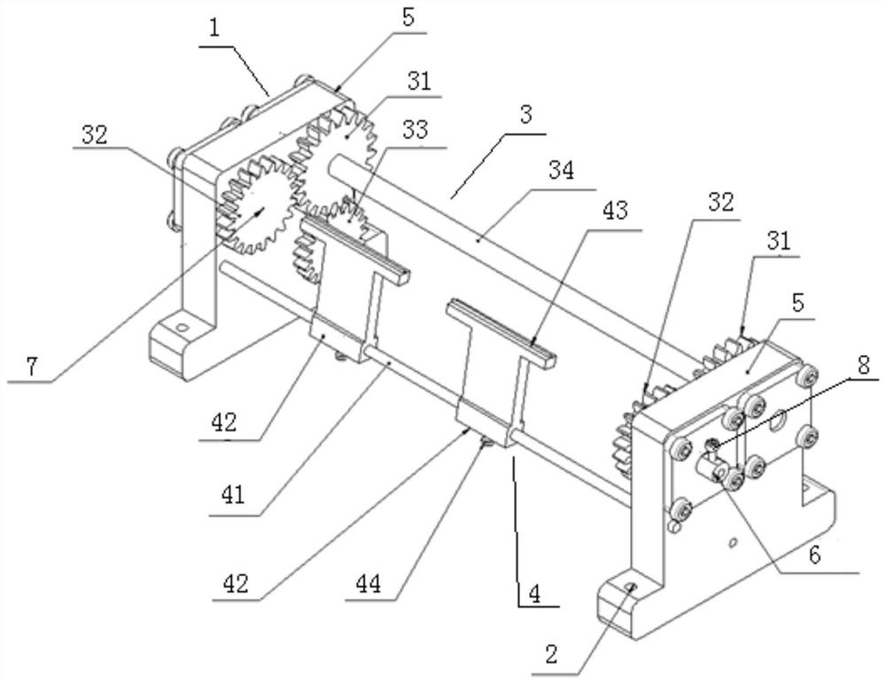
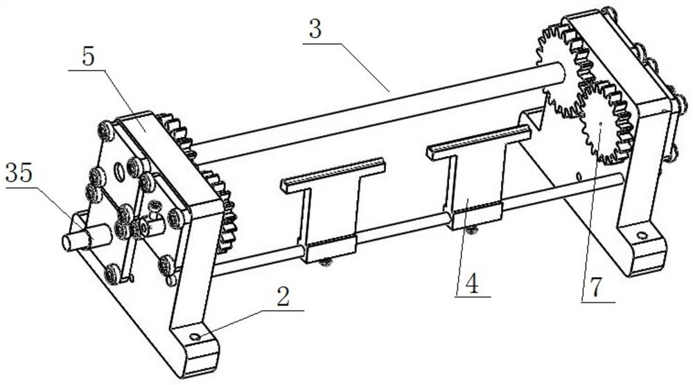
[0030] like Figure 1 to Figure 2 As shown, a self-rotating optical fiber coating mask device includes a fixed support structure 1, a drive structure 3 arranged on the fixed support structure 1 and used for optical fiber rotation, and a mask structure 4 for mask protection of the optical fiber during coating. The self-rotating optical fiber coating mask device in this embodiment has a uniform rotation speed during the coating process, and can uniformly sputter the film layer on the side of the optical fiber cylinder. The entire self-rotating optical fiber coating mask device has a separate closed structure, even if the The failure will not affect the environment of the coating chamber, the coating quality, and will not damage the coating device. The device is small in size and sturdy in structure, and is very suitable for a magnetron sputtering instrument with a small coating chamber space. The device is designed with a mask structure 4, which can realize a multi-film structu...

Embodiment 2

[0040] The present invention also provides a method for uniform coating on the side surface of an optical fiber cylinder, using the above self-rotating optical fiber coating mask device, including the following steps:

[0041] S1: Pass the optical fiber with the outer protective layer removed in sequence through the central hole 7 on the fixed shaft 6, the mask block through hole 43, and the central hole 7 on the fixed shaft 6, and fix both ends of the optical fiber to the driven gear through the screw structure 8 On the fixed shaft 6 on 32;

[0042] S2: Adjust the position of the mask block 42 on the support shaft 41, and perform mask protection on the optical fibers that do not require coating;

[0043] S3: Install the self-rotating optical fiber coating mask device in the chamber of the coating instrument;

[0044] S4: Turn on the instrument to evacuate. When the test requirements are met, turn on the stepper motor connected to the power take-off shaft 35 and adjust its sp...


PUM


Abstract

The invention discloses a self-rotating optical fiber coating mask device, which comprises a fixed support structure, a drive structure arranged on the fixed support structure and used for optical fiber rotation, and a mask structure for mask protection of the optical fiber during coating. The self-rotating optical fiber coating mask device of the present invention has a uniform rotation speed during the coating process, and can uniformly sputter a film layer on the side of the optical fiber cylinder. The entire self-rotating optical fiber coating mask device has a separate closed structure, even if there is a failure It will not affect the environment of the coating chamber, the coating quality, and will not damage the coating device. The device is small in size and strong in structure, which is very suitable for magnetron sputtering equipment, which has a small space in the coating chamber. The device is designed with a mask structure, which can realize the process of multi-film structure. In addition, this device is also suitable for side coating of other columns, and the coating equipment can be replaced by vacuum evaporation or ion coating equipment in addition to magnetron sputtering equipment.

Description

technical field [0001] The invention relates to the technical field of optical fibers, and more particularly, to a self-rotating optical fiber coating mask device and a coating method using the device. Background technique [0002] Optical fiber is a light transmission tool based on the principle of total reflection of light in fibers made of glass plastic. Based on its advantages of large communication capacity, long relay distance, no electromagnetic interference, light weight and small size, it is widely used in optical fiber. Communication has been widely used. With the rapid development of optical fiber technology, optical fiber has been widely used in communication, sensing and other fields. In the field of optical communication, optical signal detection or transmission requires optical fibers to have a certain light reflection capability, and the conventional method is to coat the surface of the optical fiber to improve the light reflection capability. In the field ...

Claims


Application Information

Patent Timeline
Patent Type & Authority Patents(China)
IPC IPC(8): C23C14/04C23C14/35C23C14/24
CPCC23C14/042C23C14/35C23C14/24
Inventor 崔俊龙江秀娟
Owner GUANGDONG UNIV OF TECH
Learn More