New energy automobile speed reducer driven gear and manufacturing process thereof

A technology of new energy vehicles and driven gears, applied in belts/chains/gears, mechanical equipment, components with teeth, etc., can solve problems such as low material utilization, high processing costs, and long production cycles, and achieve material High utilization rate, meet supporting requirements, and improve tooth surface strength

Inactive Publication Date: 2020-06-30
江苏威鹰机械有限公司
View PDF0 Cites 0 Cited by
  • Summary
  • Abstract
  • Description
  • Claims
  • Application Information

AI Technical Summary

Problems solved by technology

The driven gear of the new energy vehicle reducer is widely used in automobile manufacturing. The driven gear of the reducer has high requirements on the mechanical properties and machining accuracy of the material. The existing manufacturing process generally uses cutting and hobbing to process the tooth surface, and the metal flow line is Cutting, the internal structure of the material is loose, the production efficiency is low, the material utilization rate is low, the production cycle is long, and the processing cost is high; the tooth surface is not compact, the mechanical performance is poor, and the tooth is easy to be damaged during the working process, which is difficult to meet the needs of new energy vehicle parts. Quality requirements

Method used


Image

  • New energy automobile speed reducer driven gear and manufacturing process thereof
  • New energy automobile speed reducer driven gear and manufacturing process thereof
  • New energy automobile speed reducer driven gear and manufacturing process thereof

Examples


Embodiment

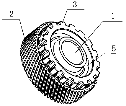
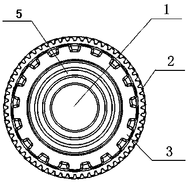
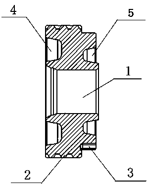
[0015] Example: see figure 1 , figure 2 with image 3 As shown, the driven gear of a new energy vehicle reducer has a hollow cylindrical structure and is forged from metal. It is provided with a center hole 1, and its outer circumferential surface is provided with helical teeth 2 and straight teeth 3, respectively. Each end surface is provided with an annular groove, the end surface adjacent to the helical tooth 2 is provided with a first annular groove 4, and the end surface adjacent to the straight tooth 3 is provided with a second annular groove 5.

[0016] The manufacturing process includes the following steps: ① blanking: cutting the required metal bar; ② heating upsetting: heating to 1090 ℃-1150 ℃ coating upsetting extrusion; ③ extrusion molding: the upsetting of the above-mentioned upsetting by a die The blank is extruded to form the first annular groove 4, the second annular groove 5 on both ends, the straight teeth 3 on the outer circumferential surface, and the central ...


PUM


Abstract

The invention discloses a new energy automobile speed reducer driven gear. The new energy automobile speed reducer driven gear is integrally of a hollow cylindrical structure, is formed by forging metal and is provided with a center hole, helical teeth and straight teeth are arranged on the circumferential face of the outer side of the center hole correspondingly, annular grooves are formed in thetwo end faces correspondingly, a first annular groove is formed in the end face adjacent to the helical teeth, and a second annular groove is formed in the end face adjacent to the straight teeth. According to the new energy automobile speed reducer driven gear, a warm-cold combined forging method is adopted, the production period is short, the material utilization rate is high, the machining cost is low, a metal streamline is not cut off, the grain structure is compact, the tooth surface strength is improved, the mechanical performance is high, and the matching requirements of new energy automobile parts can be met.

Description

Technical field [0001] The invention relates to an automobile reducer, in particular to a manufacturing process of a driven gear of a new energy automobile reducer. Background technique [0002] The reducer is a relatively precise machine, and its purpose is to reduce the speed and increase the torque. The driven gear of the reducer of new energy vehicles is widely used in automobile manufacturing. The driven gear of the reducer has high requirements on the mechanical properties and machining accuracy of the material. The existing manufacturing process generally uses cutting and hobbing to form the tooth surface, and the metal streamline is Cutting, the internal organization of the material is loose, the production efficiency is low, the material utilization rate is low, the production cycle is long, and the processing cost is high; the compactness of the tooth surface is not good, the mechanical performance is poor, the tooth is easy to be damaged during the working process, and...

Claims


Application Information

Patent Timeline
Patent Type & Authority Applications(China)
IPC IPC(8): F16H55/17F16H55/08B23P15/14
CPCB23P15/14F16H55/0806F16H55/17
Inventor 张太良王丽梅刘永康申剑苏枭鑫
Owner 江苏威鹰机械有限公司
Why Eureka
Try Eureka