Light field camera calibration method for three-dimensional topography measurement

A technology of light field camera and calibration method, which is applied in the direction of measuring devices, optical devices, instruments, etc., and can solve the problems of no public disparity map 3D shape calibration method, etc.

Active Publication Date: 2020-06-30
VOMMA (SHANGHAI) TECH CO LTD
View PDF5 Cites 16 Cited by
  • Summary
  • Abstract
  • Description
  • Claims
  • Application Information

AI Technical Summary

Problems solved by technology

At present, the light field depth estimation algorithm usually only calculates the disparity map, and few people study the process of converting the disparity map into real 3D information, that is, there is no calibration method or algorithm for converting the disparity map into 3D topography in the existing technology

Method used


Image

  • Light field camera calibration method for three-dimensional topography measurement
  • Light field camera calibration method for three-dimensional topography measurement
  • Light field camera calibration method for three-dimensional topography measurement

Examples


Embodiment Construction

[0045] The present invention will be described in detail below in conjunction with specific drawings and embodiments. The following examples will help those skilled in the art to further understand the present invention, but do not limit the present invention in any form. It should be noted that those skilled in the art can make several changes and improvements without departing from the concept of the present invention. The above all belong to the protection scope of the present invention.

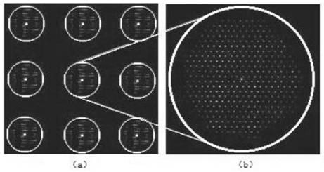
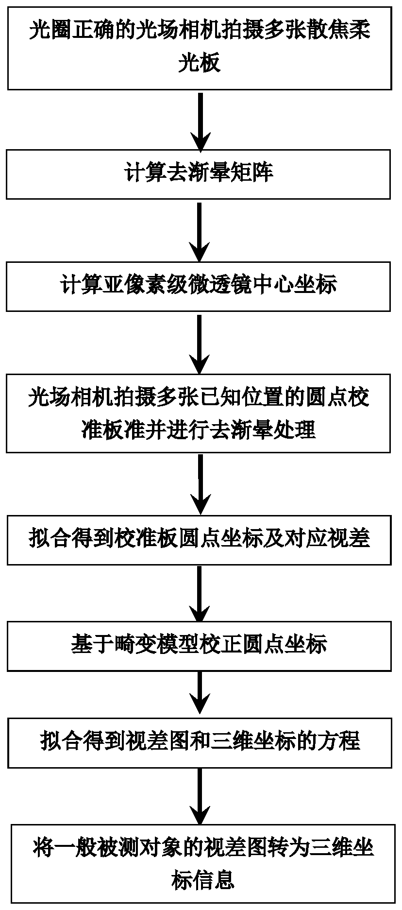
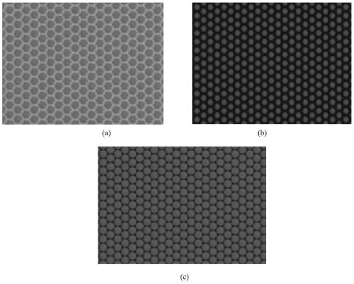
[0046] Such as figure 1 , figure 2 , image 3 , Figure 4 , Figure 5 As shown, the purpose of the present invention is to provide a light field camera calibration method for three-dimensional shape measurement, which converts the light field parallax image into spatial three-dimensional coordinate information without main lens distortion.

[0047] The technical scheme adopted in the present invention is as figure 1 The following steps are shown:

[0048] A1: Use the light field ca...


PUM


Abstract

The invention provides a light field camera calibration method for three-dimensional topography measurement, and the method comprises the steps: calibrating calibration plates at different positions in a space and corresponding light field original images, and obtaining a corresponding relation between a light field parallax image and three-dimensional space information; shooting a plurality of defocusing soft light pure color calibration plates by using a light field camera to obtain a light field white image; performing calculating according to the white image of the light field camera to obtain a vignetting removing matrix; carrying out iterative calculation to obtain a light field camera micro-lens sub-pixel-level center coordinate matrix; enabling the light field camera to shoot a plurality of dot calibration plates with known three-dimensional space positions and perform vignetting removal processing; and establishing a light field mathematical model from the three-dimensional coordinates to the parallax, and performing fitting calculation according to the light field three-dimensional imaging rule and the dot three-dimensional space information to obtain a dot center coordinate and a parallax value corresponding to dot calibration. According to the invention, a light field parallax image can be efficiently and accurately converted into three-dimensional space informationwithout main lens distortion.

Description

technical field [0001] The invention relates to the technical field of three-dimensional shape measurement, in particular to a light field camera calibration method for three-dimensional shape measurement. Background technique [0002] Three-dimensional shape measurement technology is a core technology in the field of machine vision and measurement. Three-dimensional shape measurement refers to the measurement of three-dimensional information on the surface of an object. In recent years, the emergence of light field cameras provides a new solution direction for 3D shape measurement. The biggest difference between a light field camera and a traditional two-dimensional camera is that a microlens array is added in front of the sensor, so that it can record the propagation direction of light in space, thereby forming a special original light field image, and processing the light field image After rendering, light field multi-view images, light field refocusing images and light...

Claims


Application Information

Patent Timeline
Patent Type & Authority Applications(China)
IPC IPC(8): G01B11/24G01B11/00
CPCG01B11/00G01B11/24G01B21/042
Inventor 李浩天钱至文丁俊飞
Owner VOMMA (SHANGHAI) TECH CO LTD
Why Eureka
Try Eureka