
Heat absorption experimental equipment capable of achieving visual comparison

A kind of experimental equipment and intuitive technology, applied in teaching models, instruments, educational appliances, etc., can solve problems such as inconvenient reading, achieve high accuracy, easy operation, and avoid burns.

Inactive Publication Date: 2020-06-30
CHONGQING UNIV OF ARTS & SCI
View PDF0 Cites 0 Cited by
  • Summary
  • Abstract
  • Description
  • Claims
  • Application Information

AI Technical Summary

Problems solved by technology

[0003] The present invention intends to provide a kind of endothermic experimental equipment with intuitive comparison, so as to solve the problem of inconvenient reading in common endothermic contrast experimental equipment.

Method used


Image

  • Heat absorption experimental equipment capable of achieving visual comparison
  • Heat absorption experimental equipment capable of achieving visual comparison
  • Heat absorption experimental equipment capable of achieving visual comparison

Examples


Embodiment 1

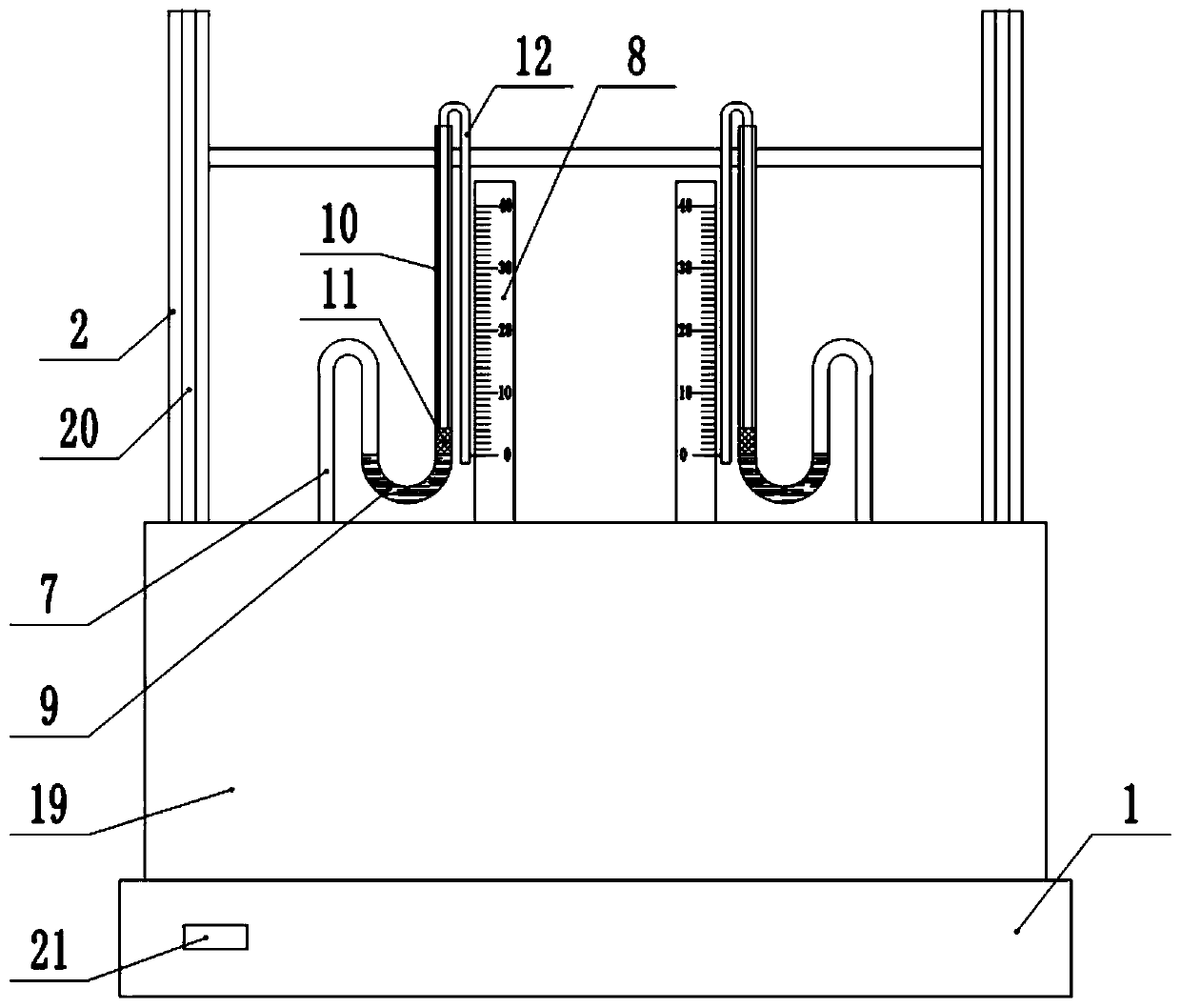
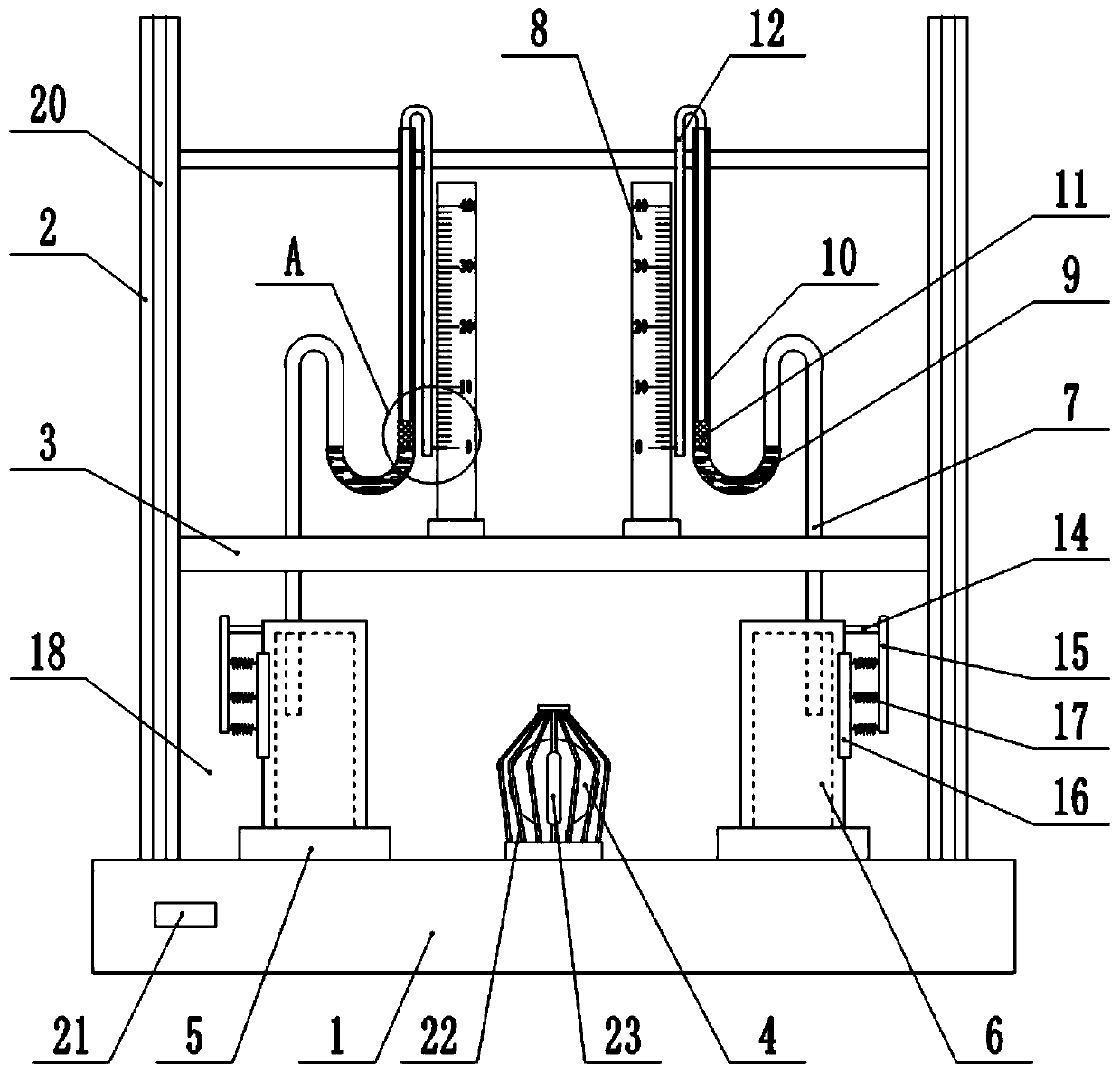
[0032] This embodiment is basically as figure 1 , figure 2 and image 3 Shown: a heat-absorbing experimental equipment for intuitive comparison, including a base 1, a frame 2 is fixedly connected to the base 1, and a partition 3 is fixedly connected to the frame 2. A heat source 4 and two endothermic detection units are installed on the base 1, and each endothermic detection unit includes a mounting base 5, a hollow and sealed cylinder 6, a gas delivery pipe 7, a detection tube and a scale 8, and the mounting base 5 It is fixedly installed on the base 1 by bolts, and the cylinder 6 is welded or fixedly installed on the mounting base 5 by bolts.

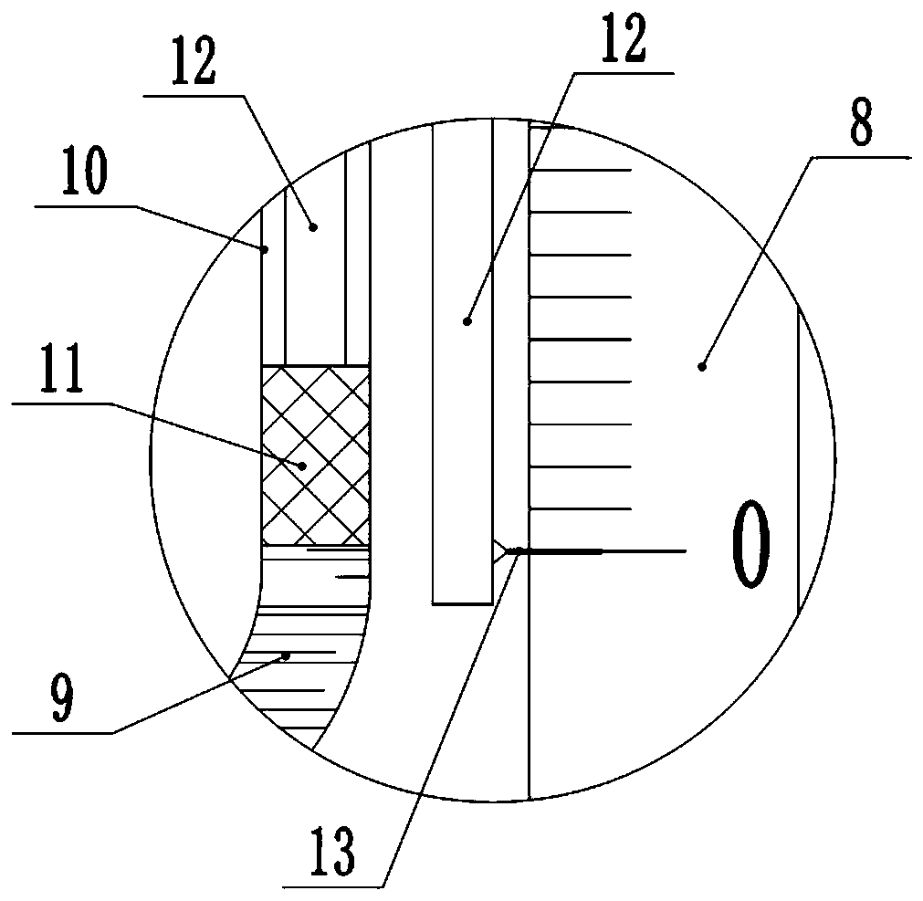
[0033] The bottom end of the air delivery pipe 7 communicates with the inside of the cylinder 6, and the detection tube includes a connected U-shaped pipe 9 and a vertical pipe 10. The top of the air delivery pipe 7 passes through the partition plate 3 and communicates with the U-shaped pipe 9 of the detection pipe. Liquid is fill...

Embodiment 2

[0042] The difference between this embodiment and the first embodiment is that the mounting seat 5 is not fixedly installed on the base 1, such as Figure 4 and Figure 5 As shown, a chute 24 is provided on the base 1, and a magnetic slider 25 is fixedly connected to the bottom surface of the mounting seat 5, and the magnetic slider 25 slides in the chute 24. In this embodiment, the magnetic slider 25 is an NdFeB magnet. . The inside of the base 1 is provided with a cavity 26, and the electromagnet 27 controlled by the switch 21 is installed in the cavity 26; the partition 3 is provided with a through groove for the horizontal movement of the air pipe 7, and the scale 8 is horizontally slidably connected to the partition 3 . The endothermic detection unit also includes a moving block 28, which is horizontally slidably connected to the partition plate 3, and the top surface of the moving block 28 is fixedly connected with a support rod 29, and the top of the support rod 29 is...

Embodiment 3

[0045] The difference between this embodiment and Embodiment 1 is that the liquid trichloroethane is filled in the airbag 23, and the boiling point of trichloroethane is 74-76°C. Ethyl chloride absorbs heat, and the temperature rises gradually until reaching the boiling point of trichloroethane. In the process, trichloroethane evaporates from liquid to gaseous state, and the internal pressure of the air bag 23 increases, so the volume of the air bag 23 increases, and the air bag 23 The effect of increasing the volume is more obvious than that of the airbag 23 in the first embodiment, and the user can identify it more easily to prevent the occurrence of burns.


PUM


Abstract

The invention relates to the technical field of physical experiment equipment. The invention particularly discloses heat absorption experimental equipment capable of achieving visual comparison. The equipment includes a base, and a frame is fixedly connected to the base. A partition plate is fixedly connected in the frame; a heating source and two heat absorption detection units are mounted on thebase; each heat absorption detection unit comprises a hollow and sealed cylinder, a gas conveying pipe, a detection pipe and a graduated scale; the bottom end of the gas conveying pipe communicates with the interior of the cylinder; the detection pipe comprises a U-shaped pipe and a vertical pipe which are communicated, the top end of the gas conveying pipe penetrates through the partition plateand is communicated with the U-shaped pipe of the detection pipe, liquid is contained in the U-shaped pipe, a buoy is placed in the vertical pipe, the buoy is fixedly connected with a special-shaped supporting rod, and a pointer pointing to the graduated scale is arranged at the end, extending out of the vertical pipe, of the special-shaped supporting rod; the cylinder is fixedly connected with afixing plate, an arc-shaped pressing plate is arranged between the fixing plate and the cylinder, the arc-shaped pressing plate is fixedly connected with the fixing plate through an elastic piece, andthe arc-shaped pressing plate abuts against the side wall of the cylinder. According to the invention, the pointer is utilized to visually and rapidly realize reading, and a user does not need to adjust the position of himself / herself.

Description

technical field [0001] The invention relates to the technical field of physical experiment equipment, and specifically discloses a heat-absorbing experimental equipment for visual comparison. Background technique [0002] The endothermic comparison test equipment can intuitively compare the heat absorption effects of different substances. Ordinary endothermic comparison test equipment usually uses the difference in the rise height of the liquid to preliminarily judge the heat absorption effect of the substance, but in order to obtain the final result, it is necessary to read the liquid The height value of the surface is then converted to obtain the heat absorption rate of the substance. When reading the height value of the liquid level, the user needs to adjust his position so that his eyes are consistent with the height of the liquid level, otherwise the read liquid level value is inaccurate, resulting in a large error in the final experimental data. And every time the use...

Claims


Application Information

Patent Timeline
IPC IPC(8): G09B23/16
CPCG09B23/16
Inventor 程正富伏春平
Owner CHONGQING UNIV OF ARTS & SCI
Learn More