Straight cylinder type high-pressure cleaning device and high-pressure cleaning system

A high-pressure cleaning, straight-tube technology, applied in mechanical equipment, variable displacement pump components, cleaning methods and utensils, etc., can solve the problems of poor flexibility, unfavorable liberation of the operator's hands, etc., to achieve easy storage, improve cleaning effect, Ease of use

Pending Publication Date: 2020-07-03
苏州贝米科技有限公司
View PDF1 Cites 3 Cited by
  • Summary
  • Abstract
  • Description
  • Claims
  • Application Information

AI Technical Summary

Problems solved by technology

[0008] Finally, two-handed work is required during operation, which is obviously not conducive to freeing the operator's hands. Compared with one-handed work, two-handed work has certain restrictions on the use angle, and the flexibility of use is poor.

Method used


Image

  • Straight cylinder type high-pressure cleaning device and high-pressure cleaning system
  • Straight cylinder type high-pressure cleaning device and high-pressure cleaning system
  • Straight cylinder type high-pressure cleaning device and high-pressure cleaning system

Examples


Embodiment 1

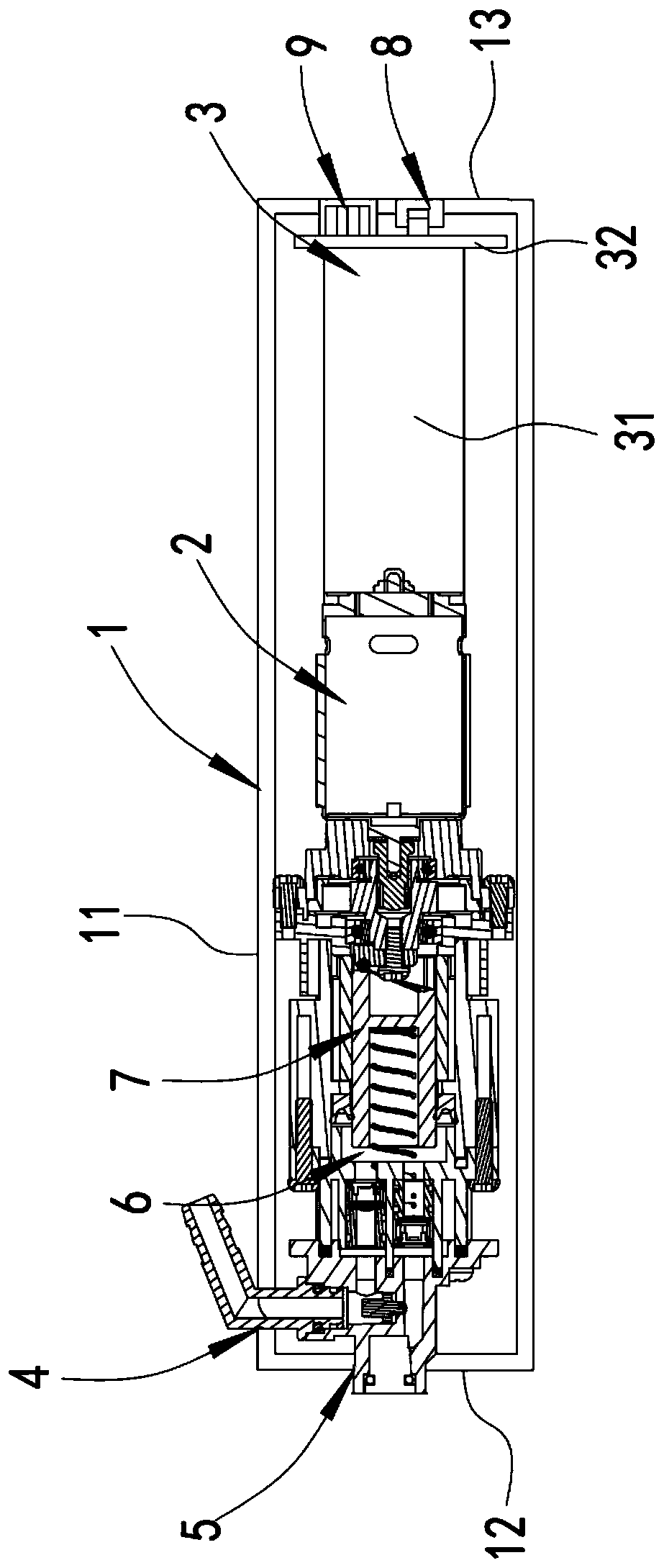
[0059] as attached figure 1 , attached figure 2 As shown, the fluid inlet 4 and the fluid outlet 5 are connected to the fluid entry and exit control mechanism located in the casing 1, the fluid entry and exit control mechanism is preferably close to the front end of the casing 1, and the fluid entry and exit control mechanism is located in the piston. 7 When moving from the far end (the end where the entire device points to the front when the user uses it) to the proximal end (the end where the entire device points to the rear when the user uses it) (during suction), only the external fluid is allowed to be sucked in by the fluid inlet 4 In the pressurized chamber 6, the fluid in the pressurized chamber 6 cannot be discharged through the fluid outlet 5; and when the piston 7 moves from the proximal end to the distal end (when squeezed), the external fluid is not allowed to pass through the fluid inlet 4 is sucked into the pressurized chamber 6, and only the fluid in the pre...

Embodiment 2

[0071] The difference between this embodiment and the above-mentioned embodiment 1 is that: Figure 5 As shown, the fluid inlet 4 is arranged at the proximal end of the housing 1, preferably at the end face of the proximal end, that is, the fluid inlet 4 includes at least one hole on the end panel 13 at the proximal end of the housing. , since there is a relatively large distance between the fluid inlet 4 and the far-end fluid entry and exit control mechanism, a fluid channel 300 is also provided between the fluid inlet 4 and the inlet of the fluid entry and exit control mechanism, and the fluid The channel 300 is preferably disposed inside the housing 1 , of course, it can also be disposed outside the housing 1 in other embodiments.

[0072] At this time, the fluid inlet 4 can also vertically extend outward for a certain distance from the proximal end panel 13 of the housing 1 , so as to facilitate detachable connection with the pipe joint 40 or an external pipe. Of course, ...


PUM


Abstract

The invention discloses a straight cylinder type high-pressure cleaning device and a high-pressure cleaning system. The straight cylinder type high-pressure cleaning device comprises a shell, a driving structure, a circuit structure, a fluid inlet, a fluid outlet and a piston, the piston is driven by the driving structure to move linearly and reciprocally so as to introduce fluid into a pressurizing cavity from the fluid inlet and discharge the pressurized fluid from the fluid outlet, the shell is a straight cylinder which is internally provided with a cavity and extends along a straight line,and an axis of the shell and an axis of a power output shaft of the driving structure are coaxial with or parallel to an axis of the piston. According to the device and the system, the shell is cylindrical, the occupied space can be effectively reduced, and miniaturization production of equipment is facilitated. When in use, a user can hold any position of the shell, so that the load of palms andarms of an operator can be effectively reduced, and the use is convenient; and meanwhile, single-hand operation is conveniently realized, the operation flexibility is greatly improved, meanwhile, double-hand operation is not needed, other operations can be carried out by one hand, and the design is more user-friendly.

Description

technical field [0001] The invention relates to cleaning equipment, in particular to straight cylinder high-pressure cleaning equipment and a high-pressure cleaning system. Background technique [0002] A high-pressure cleaner is a device that uses a reciprocating piston to compress the liquid in the cylinder to pressurize it to form a high-pressure water flow to clean the object. It can be used to clean cars, floors, walls, doors and windows, etc. With the continuous improvement of people's living standards, high-pressure cleaners are also favored by more and more families. [0003] Traditional high-pressure cleaners mainly refer to hand-push high-pressure cleaners, which use carts to move heavy bodies. Due to their large volume and weight, they are poor in portability and limited in scope of use. There are still many inconveniences. [0004] In order to satisfy users in home and outdoor activities, it can realize convenient cleaning and the machine is easy to carry. At ...

Claims


Application Information

Patent Timeline
Patent Type & Authority Applications(China)
IPC IPC(8): B08B3/02B08B13/00F04B53/00F04B53/16F04B53/14F04B17/03F04B1/14F04B1/12
CPCB08B3/026B08B13/00B08B2203/0217B08B2203/0223B08B2203/027B08B2203/0282F04B1/124F04B1/14F04B1/145F04B17/03F04B53/00F04B53/14F04B53/16
Inventor 刘良兵赵殿虎
Owner 苏州贝米科技有限公司
Why Eureka
Try Eureka