Rotary clamping system of mechanical gripper

A mechanical gripper and rotating fixture technology, applied in the direction of manipulators, program-controlled manipulators, chucks, etc., can solve the problems of vibration of the structure, less translational applications, and influence on the stability of the structure, so as to achieve uniform contact force and stable clamping of objects. , the effect of reliable work

Active Publication Date: 2020-07-03
DALIAN MARITIME UNIVERSITY
View PDF7 Cites 1 Cited by
  • Summary
  • Abstract
  • Description
  • Claims
  • Application Information

AI Technical Summary

Problems solved by technology

[0003] The traditional mechanical gripper movement forms are mainly rotary type and translation type. Although the rotary type mechanical gripper has a simple structure and is easy to manufacture, when grabbing workpieces of different sizes, the position of its axis will change accordingly, causing the entire structure to change. Vibration affects the stability of the structure; when the translational mechanical gripper clamps circular parts, the diameter change of the workpiece does not affect the position of its axis, so it is suitable for clamping workpieces with a large diameter variation range, but because of its complex structure, translational applications less

Method used


Image

  • Rotary clamping system of mechanical gripper
  • Rotary clamping system of mechanical gripper
  • Rotary clamping system of mechanical gripper

Examples


Embodiment Construction

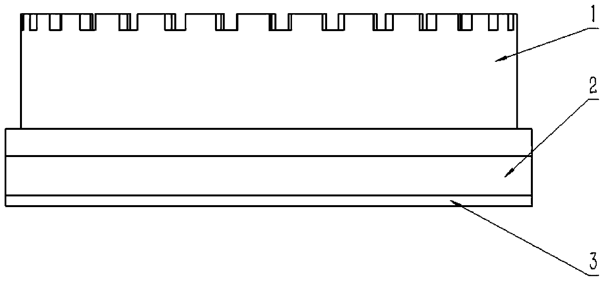
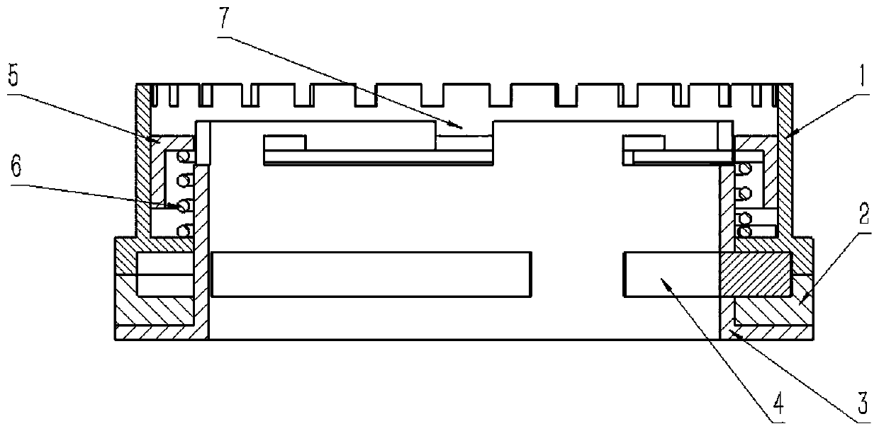
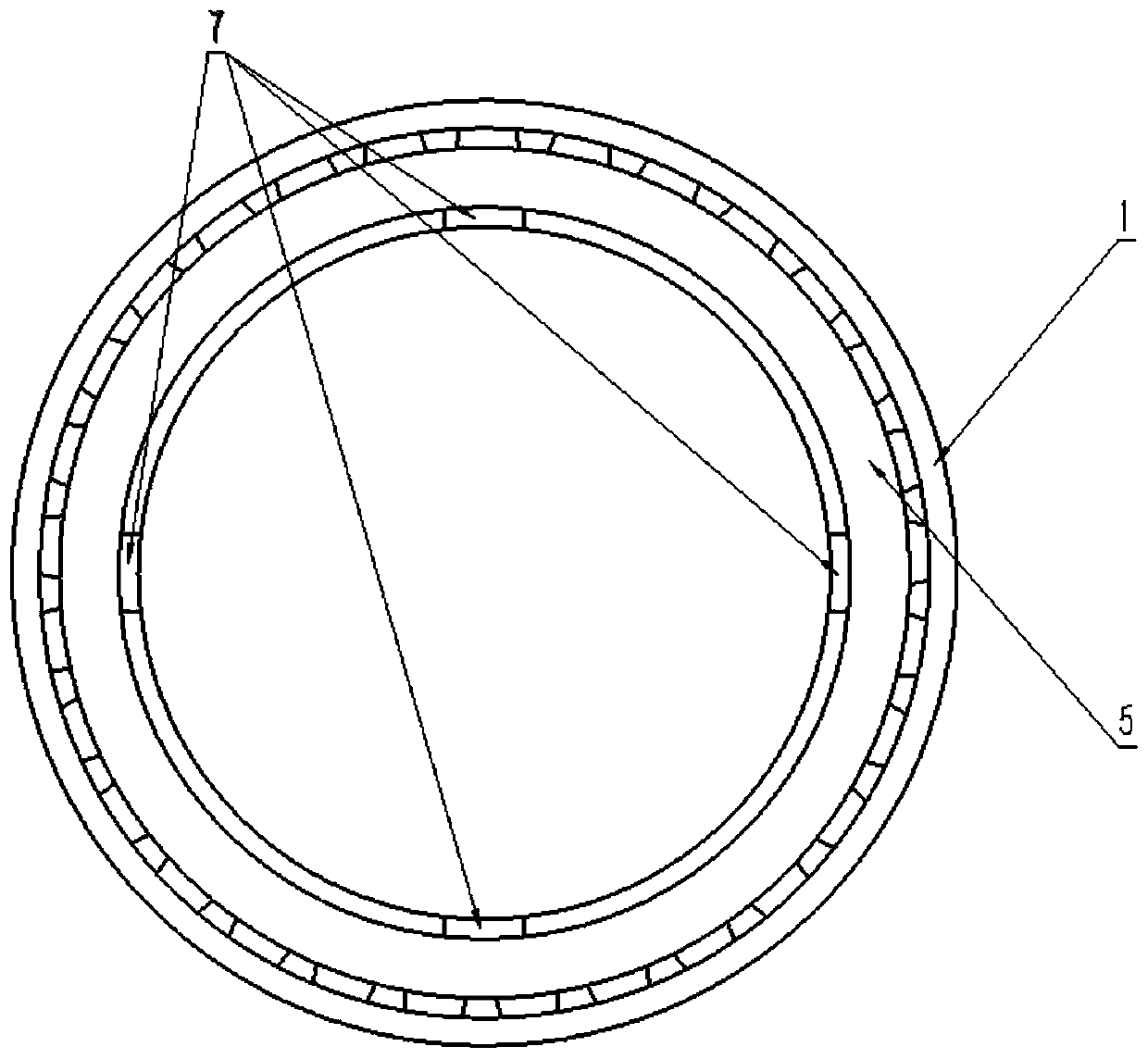
[0032] The present invention will be further described below in conjunction with the accompanying drawings. Such as Figure 1-8 As shown, a rotary clamping system of a mechanical gripper includes a rotary clamping device 14 and a power device 12, the hollow main shaft 3 of the rotary clamping device 14 is rigidly connected to the front end of the mechanical arm 15, and the power device 12 is installed At the oblique rear of the rotating clamping device 14 and on the side of the head end of the mechanical arm 15, the output shaft of the power device 12 is connected to the intermittent gear 13; the intermittent gear 13 is engaged with the rotating housing 1 to drive the rotating housing 1 to rotate;

[0033] The rotating clamping device 14 includes a hollow main shaft 3, a high-strength spring 6, a rotating clamp 4, a clamp installation sleeve 2, a tail cover 5 and a rotating housing 1. The head of the hollow main shaft 3 is a flange, and the tail is a circle. The high-strength...


PUM


Abstract

The invention discloses a rotary clamping system of a mechanical gripper. The rotary clamping system of the mechanical gripper comprises a rotary clamping device and a power device, a hollow main shaft of the rotary clamping device is in rigid connection with the front end of a mechanical arm, the power device is installed at the oblique rear of the rotary clamping device and on the side of the head end of the mechanical arm, an output shaft of the power device is connected with an intermittent gear, and the intermittent gear is engaged with a rotary shell to drive the rotary shell to rotate.According to the rotary clamping system of the mechanical gripper, the rotary shell and a clamp mounting shaft sleeve at the tail part of the mechanical gripper are mainly utilized to drive a rotary clamp inside the mechanical gripper to rotate, the deformation of a high-strength spring forms screwing motion, then the clamping and releasing actions of the rotary clamp are formed, the rotary clampis rotated out and rotated in by combining a mechanical structure, an object is clamped more stably, the contact stress with the clamped object is uniform, the selectable range of the size of the clamped object is relatively large, and the controllability is higher than that of a traditional mechanical gripper.

Description

technical field [0001] The invention relates to a mechanical clamping device, in particular to a rotary clamping system of a mechanical gripper. Background technique [0002] The mechanical gripper is a new type of device developed in the mechanized and automated production process. In the modern production process, mechanical grippers are widely used in automatic production lines. The development and production of mechanical grippers has become a rapidly developing new technology in the high-tech field, which further promotes the use of mechanical grippers. The development enables the mechanical gripper to better realize the organic combination with mechanization and automation. [0003] The traditional mechanical gripper movement forms are mainly rotary type and translation type. Although the rotary type mechanical gripper has a simple structure and is easy to manufacture, when grabbing workpieces of different sizes, the position of its axis will change accordingly, causi...

Claims


Application Information

Patent Timeline
Patent Type & Authority Applications(China)
IPC IPC(8): B25J15/00B25J15/02B25J9/00
CPCB25J15/0028B25J15/02B25J9/00
Inventor 徐敏义仇伟晗李文祥王梓丞刘翔宇陈天予付先平张爱东
Owner DALIAN MARITIME UNIVERSITY
Why Eureka
Try Eureka