Torsional spring type assisting joint and assisting walking robot

A technology of joints and torsion springs, which is applied in the field of torsion spring-type power-assisted joints and walking-assisted robots, which can solve problems such as complex structures, comfort discounts, and self-heavy power-assisted joints, and achieve broad market prospects, simple and light structure, and comfortable wearing Good results

Pending Publication Date: 2020-07-03
SHENYANG SIASUN ROBOT & AUTOMATION
View PDF0 Cites 2 Cited by
  • Summary
  • Abstract
  • Description
  • Claims
  • Application Information

AI Technical Summary

Problems solved by technology

[0003] Most of the currently existing power-assisted joints are driven by motors. Electric-driven power-assisted joints use motors as driving components, resulting in heavy weight and complex structures. Due to the introduction of motors, the cost of power-assisted joints has increased significantly. Maintenance And the difficulty of maintenance increases, and the reliability of joint work decreases
Due to the noise generated when the motor is working, when the user wears the power-assisted joint, the wearing comfort will be greatly reduced
Since the motor needs to consume electric energy, the battery life of the electric drive power-assisted joint also has a large defect.

Method used


Image

  • Torsional spring type assisting joint and assisting walking robot
  • Torsional spring type assisting joint and assisting walking robot
  • Torsional spring type assisting joint and assisting walking robot

Examples


Embodiment Construction

[0028] In order to make the object, technical solution and advantages of the present invention clearer, the present invention will be further described in detail below in conjunction with the accompanying drawings and specific embodiments. It should be understood that the specific embodiments described here are only used to explain the present invention, but not to limit the present invention.

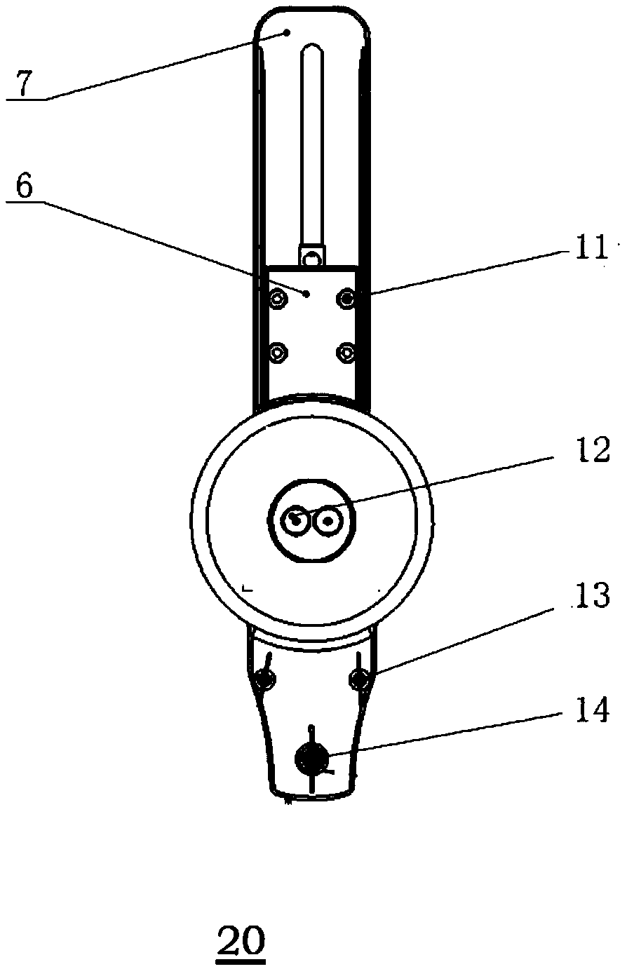
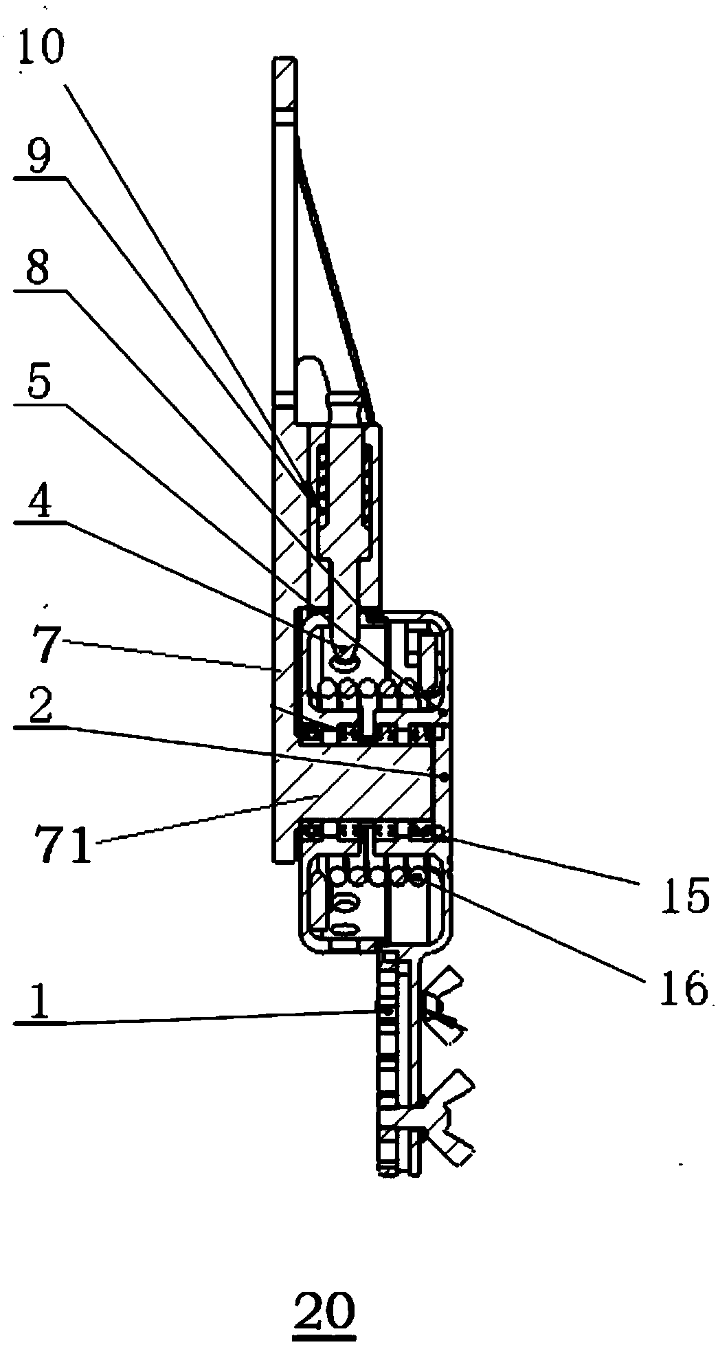
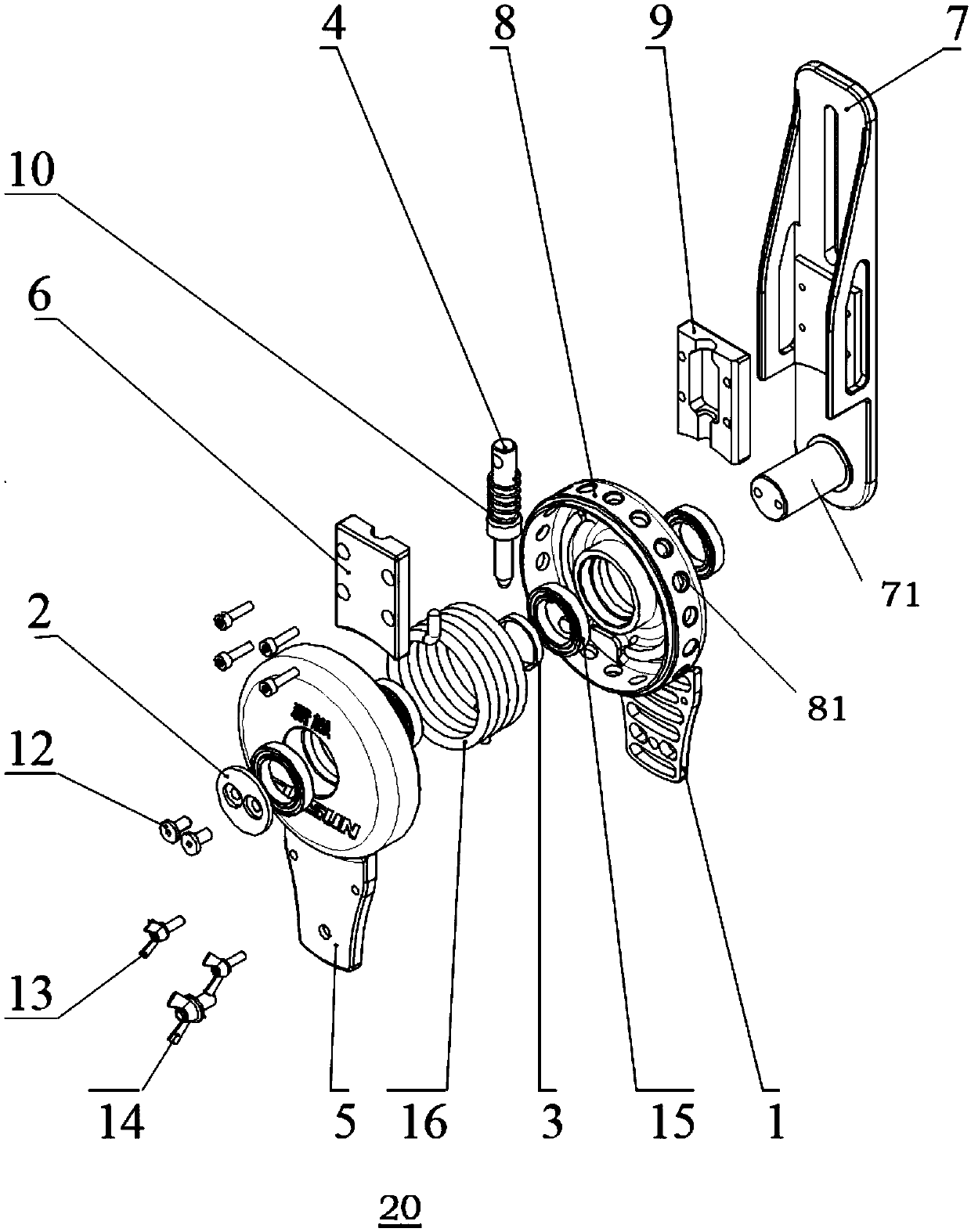
[0029] refer to Figure 1 to Figure 3 As shown, a torsion spring type power-assisted joint 20 according to an embodiment of the present invention is schematically shown. The torsion spring type power-assisted joint 20 includes: an elastic drive device 16, a drive device shell, a waist fixing device and a circumferential fixing device;

[0030] The elastic driving device 16 is arranged in the housing of the driving device;

[0031] The drive device housing includes a joint outer cover 5 and a joint inner cover 8. One end of the elastic drive device 16 is arranged on the joint outer co...


PUM


Abstract

The invention discloses a torsional spring type assisting joint. The torsional spring type assisting joint includes an elastic driving device, a driving device shell, a waist fixing device and a circumference fixing device. The elastic driving device is arranged in the driving device shell. The driving device shell comprises a joint outer cover and a joint inner cover; a plurality of bolt holes matched with a circumference fixing device are placed on the periphery of the joint inner cover. The waist fixing device includes a waist adjusting plate and a circular shaft; the driving device shell is placed on the circular shaft and can rotate relative to the circular shaft. The circumference fixing device is inserted into the circumference circular hole of the joint inner cover and comprises abolt, a thrust spring and a bolt fixing plate. The thrust spring is placed in a sleeved manner on the bolt and one end of the thrust spring abuts against the inner wall of a bolt fixing plate to makethe bolt stretch out of the bolt fixing plate and match in the bolt hole in a pushing mode. The invention further discloses an assisting walking robot. The assisting walking robot can solve the problems of big dead-weight, low reliability, high cost and high noise that an electric driving assisting joint cannot deal with.

Description

technical field [0001] The invention relates to the field of medical equipment, in particular to a torsion spring type power-assisted joint and a walking-assisted robot. Background technique [0002] At present, the number of robotic devices in the field of rehabilitation medicine at home and abroad is gradually increasing, and the power-assisted joint is a type of rehabilitation medical equipment that can help patients with walking impairments recover their independent walking ability. [0003] Most of the currently existing power-assisted joints are driven by motors. Electric-driven power-assisted joints use motors as driving components, resulting in heavy weight and complex structures. Due to the introduction of motors, the cost of power-assisted joints has increased significantly. Maintenance And the difficulty of maintenance increases, and the reliability of joint work decreases. Since the motor produces a certain amount of noise, when the user wears the power-assisted...

Claims


Application Information

Patent Timeline
Patent Type & Authority Applications(China)
IPC IPC(8): B25J17/00B25J17/02A61H3/04
CPCA61H3/04B25J17/00B25J17/02
Inventor 李刚曲道奎邹风山徐方邸霈宋吉来
Owner SHENYANG SIASUN ROBOT & AUTOMATION
Why Eureka
Try Eureka