
Buoy for aerator

An aerator and buoy technology, applied in the field of aerator accessories, can solve the problems of poor aeration effect, sewage purification not up to expectations, aerator can not play a good treatment effect, etc., to improve the flexibility of use , easy to adjust the effect

Inactive Publication Date: 2020-07-03
扬州美和环保科技有限公司
View PDF0 Cites 0 Cited by
  • Summary
  • Abstract
  • Description
  • Claims
  • Application Information

AI Technical Summary

Problems solved by technology

[0003] At present, there are many types of aerators, among which the buoy type aerator can work in soft foundation environments such as oxidation ponds, fish ponds, landscape lakes, sewage channels, rivers, etc. The existing buoy type aerators use buoys The buoyancy floating on the water surface is supported. The existing buoy is connected to the aerator through a fixed-length connecting rod. During the use of the aerator, the purification of the water body is limited to its own installation depth, and it can only divert water. The sewage near the tank is treated, and the use of aerators in large lakes, ponds and other deep water bodies cannot play a good role in treatment. The purification of sewage at relatively deep water levels may not achieve the expected goal, and the aeration effect is poor. Difference

Method used


Image

  • Buoy for aerator
  • Buoy for aerator
  • Buoy for aerator

Examples


specific Embodiment approach

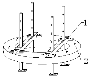
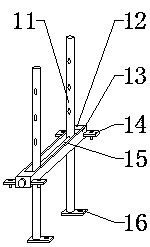
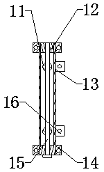
[0022] Specific implementation method: when in use, the staff first connects and fixes the four stabilizing plates 16 with the aerator through bolts, and then the staff rotates the insertion rod 15. Since the insertion rod 15 is connected with the locking block 12 through threads, the insertion rod 15 rotates and moves forward at the same time, so that the insertion rod 15 is separated from the locking block 12, and then continues to move the insertion rod 15 forward to realize the removal of the insertion rod 15 from the frame 13 and the two connecting rods 11, and then the staff moves up and down The buoy main body 2, the buoy main body 2 moves up and down to drive the frame 13 to move up and down along the connecting rod 11, when the buoy main body 2 moves to a suitable distance from the aerator, the staff will insert the rod 15 through the frame 13 again, And pass through suitable fixing holes on the two connecting rods 11, and then connect with the locking block 12 by thre...


PUM


Abstract

The invention provides a buoy for an aerator. The buoy comprises a buoy main body, a connecting rod, a locking block, a frame, a connecting block, an inserting rod and a stabilizing plate, wherein theconnecting block is welded at the outer end of the frame, the locking block is welded at the bottom end in the frame, the left end face of the locking block is attached to the rear portion of the left wall in the frame, the right end face of the locking block is attached to the rear portion of the right wall in the frame, the connecting rod is mounted at the upper end of the frame, the connectingrod penetrates the frame and extends to the lower end of the frame, the connecting rod is mounted on the front side of the locking block, the stabilizing plate is welded to the lower end of the connecting rod, the stabilizing plate is installed on the lower side of the frame, the inserting rod is installed at the front end of the frame, the inserting rod penetrates through the frame and the connecting rod and extends into the locking block, and the frame and the connecting block are installed at the upper end of the buoy main body. According to the invention, the lifting adjusting function isachieved through the design, flexibility is improved, the structure is reasonable, using flexibility is good, and depth adjusting is convenient.

Description

technical field [0001] The invention relates to a buoy for an aerator, which belongs to the technical field of aerator accessories. Background technique [0002] The aerator injects "micro-bubbles" directly into the untreated sewage through the diffuser impeller. Under the joint action of the coagulant and flocculant, the suspended solids undergo physical and chemical flocculation, thereby forming large suspended solids. Flock, under the buoyancy of the bubble group, the "floc" floats to the liquid surface to form scum. [0003] At present, there are many types of aerators, among which the buoy type aerator can work in soft foundation environments such as oxidation ponds, fish ponds, landscape lakes, sewage channels, rivers, etc. The existing buoy type aerators use buoys The buoyancy floating on the water surface is supported. The existing buoy is connected to the aerator through a fixed-length connecting rod. During the use of the aerator, the purification of the water bod...

Claims


Application Information

Patent Timeline
Patent Type & Authority Applications(China)
IPC IPC(8): C02F7/00
CPCC02F7/00Y02W10/10
Inventor 郭辉
Owner 扬州美和环保科技有限公司
Learn More