
A floating breakwater with wave power generation function and fish farming function

A floating breakwater and breakwater technology, which is applied to breakwaters, ocean energy power generation, hydroelectric power stations, etc., can solve the problems of unsatisfactory long-period wave elimination effect, neglect of development and utilization of breakwaters, and single function of floating breakwaters. Disturb the wave propagation trajectory, facilitate aging and replacement, improve the effect of application value and economic value

Active Publication Date: 2021-12-28
CHINA NAT OFFSHORE OIL CORP +1
View PDF0 Cites 0 Cited by
  • Summary
  • Abstract
  • Description
  • Claims
  • Application Information

AI Technical Summary

Problems solved by technology

[0004] 1. The design of the existing floating breakwater mainly focuses on the improvement of the wave absorption performance of the breakwater, ignoring the development and utilization of other functions of the breakwater, resulting in a single function of the existing floating breakwater
[0005] 2. Most of the existing floating breakwaters mainly rely on the way of reflecting incident waves to achieve the purpose of reducing waves, ignoring the application of other methods such as disturbing wave propagation trajectory and dissipating wave energy, which leads to the short-period wave impact of existing floating breakwaters. The wave-absorbing effect is better, but the wave-absorbing effect is not ideal for long-period waves
[0006] 3. According to the research and experiments of wave theory, 98% of the total wave energy is concentrated in the water depth range from the surface layer of the water body to three times the wave height below the water surface. Shallow, can only block waves and currents within a certain depth below the water surface

Method used


Image

  • A floating breakwater with wave power generation function and fish farming function
  • A floating breakwater with wave power generation function and fish farming function
  • A floating breakwater with wave power generation function and fish farming function

Examples


Embodiment Construction

[0074] DRAWINGS The present invention is further illustrated, but the present invention is not limited to the following embodiments.

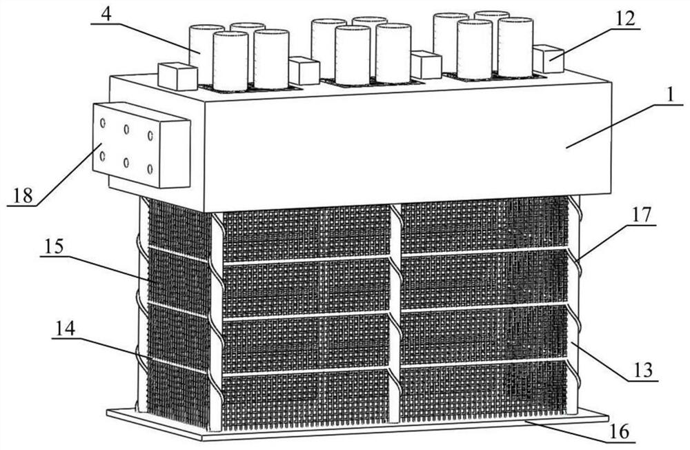
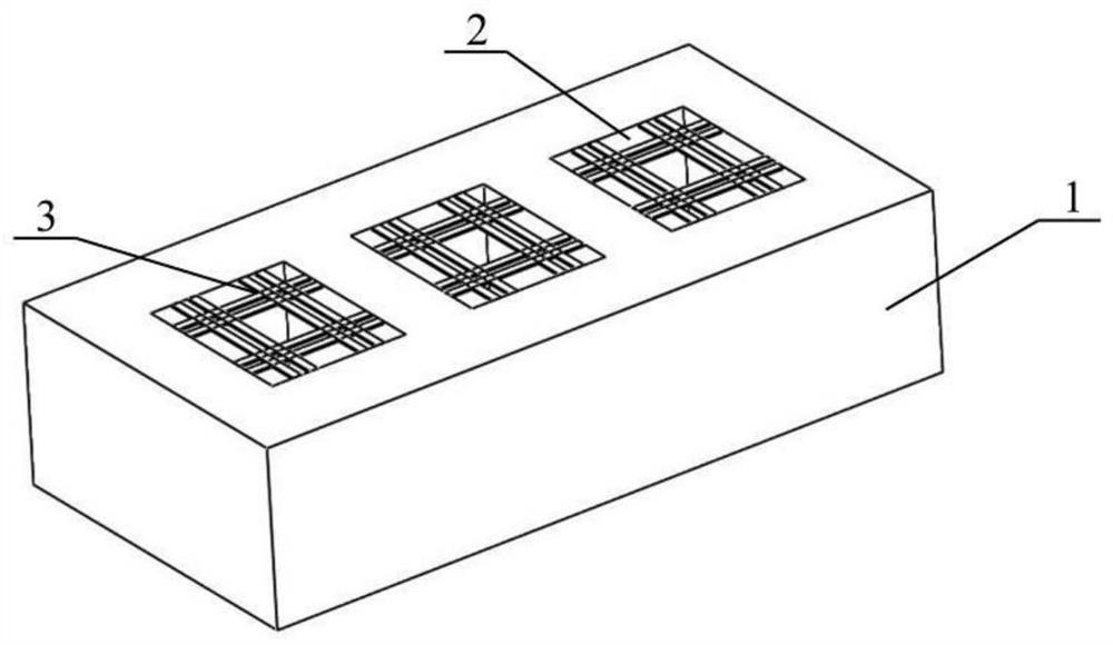
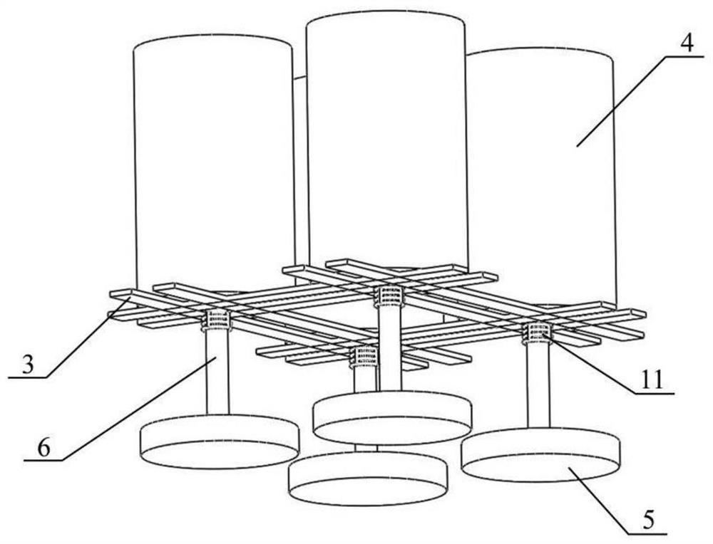
[0075] like Figures 1 to 10 , The wave energy function both aquaculture and functions floating breakwaters of the present invention, comprises a wave suppression structure generator, fish farming apparatus, a connection structure and mooring system.

[0076] In this embodiment, if figure 2 , The wave suppression structure comprises a rectangular cross section 1 levee breakwater, the breakwater through the dike rectangular moonpool 2 and arranged on top of the moonpool 2 crossbars 3. Pool 2 months were provided, uniformly distributed along a longitudinal direction of the breakwater levee; crossbars 3 were three groups of eight, the font rendering well distributed. Breakwater levee crossbars 3 and 1 by a steel material. The present invention uses a rectangular parallelepiped containing the dike 1 moonpool 2, which may ensure excellent clipping perfor...


PUM


Abstract

The invention discloses a floating breakwater which has both the function of wave energy generation and the function of fish farming. The floating breakwater includes a wave-dissipating structure, a power generation device and a fishery breeding device; the wave-dissipating structure includes a breakwater embankment, a number of moon pools are arranged on the breakwater embankment, and a number of cross braces are arranged on the top of the moon pool; the power generation device is fixed on the cross brace Above; the fish farming device is located at the lower part of the breakwater embankment. The present invention can effectively save materials and reduce engineering cost by adopting a cuboid embankment body containing a moon pool; by arranging a vertically moving power generation device, the wave energy can be converted into electric energy; It can improve its economy, disturb the wave propagation trajectory and dissipate wave energy; by adopting the column with spiral rising wing plate, the vortex induced motion can be effectively avoided; by setting the heave plate, the movement of the breakwater can be reduced to achieve the best consumption. wave effect.

Description

Technical field [0001] The present invention relates to a floating breakwater one kind of wave energy function both aquaculture and function, belonging wave power, fish farming and breakwater BACKGROUND clipping engineering. Background technique [0002] In recent years, the rise of ocean development, a large number of floating structures are used in the vast waters, in order to avoid the waves offshore structures suffered due to intrusion and damage, floating breakwater has been widely used. Floating breakwater has the following advantages: 1, a wide range of applications waters; 2, lower project cost and not affect water depth; 3, water flow and allow migratory fish and other marine life; 4, the construction is simple, easy maintenance. [0003] However, the existing floating breakwater still exist the following three major disadvantages: [0004] First, the existing floating breakwater design focuses on improving the performance of the breakwater wave cancellation, ignoring th...

Claims


Application Information

Patent Timeline
Patent Type & Authority Patents(China)
IPC IPC(8): E02B3/06E02B9/08F03B13/18A01K61/60A01K61/65
CPCE02B3/062E02B9/08F03B13/1845A01K61/60A01K61/65Y02P60/60Y02E10/30Y02A10/11Y02A40/81
Inventor 邓小康谢文会谢彬李阳韩旭亮赵晶瑞
Owner CHINA NAT OFFSHORE OIL CORP
Learn More