Revolving door with automatic dust removal function

An automatic dust removal and revolving door technology, applied in the field of revolving doors, can solve the problems of inhaling too much dust, affecting the appearance of large shopping malls and office buildings, increasing the workload of cleaning staff, etc., and reducing the workload.

Active Publication Date: 2020-07-03
抚州市中小企业服务有限公司
View PDF6 Cites 10 Cited by
  • Summary
  • Abstract
  • Description
  • Claims
  • Application Information

AI Technical Summary

Problems solved by technology

[0003] When there is a large flow of people in the halls of large shopping malls and office buildings, the coming and going crowd will carry a lot of dust, which will cause a lot of dust to adhere to the floor mat at the lower end of the revolving door, and the dust will float as people walk, making People inhale too much dust, which is harmful to people's health. In addition, for the normal operation of la

Method used


Image

  • Revolving door with automatic dust removal function
  • Revolving door with automatic dust removal function
  • Revolving door with automatic dust removal function

Examples


Embodiment 1

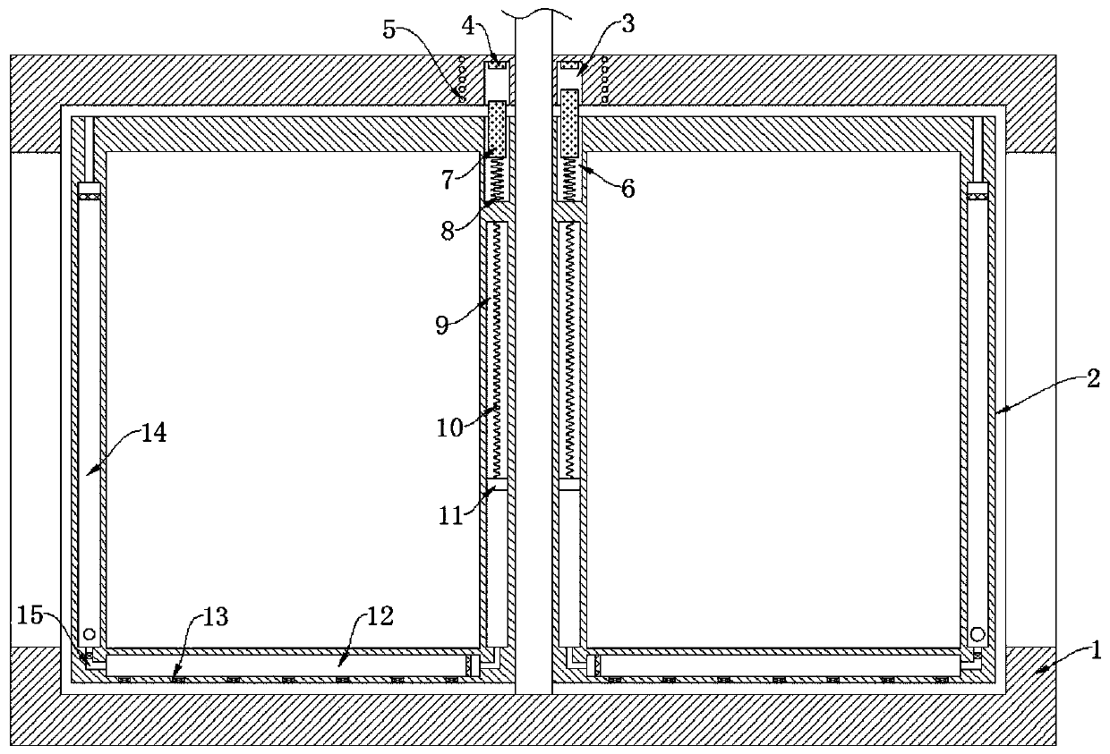
[0022] refer to figure 1 , a revolving door with automatic dust removal function, comprising a cylindrical door frame 1, the inner wall of the cylindrical door frame 1 is rotatably connected with a rotating shaft, and the rotating shaft is driven by an external drive motor, which is the prior art, and the side walls of the rotating shaft are evenly distributed and fixedly connected with multiple The revolving door frame 2, the cylindrical door frame 1 and the inner walls of the revolving door frame 2 are fixedly connected with glass, the side wall of the revolving door frame 2 close to the rotating shaft is provided with a slide chamber 9, and the inner top of the slide chamber 9 is elastically connected with a slide plug 11 through a conductive spring 10 , and the sliding plug 11 is slidingly connected with the inner wall of the sliding plug chamber 9, and a through hole communicating with the outside world is provided above the inner wall of the sliding plug chamber 9 to bala...

Embodiment 2

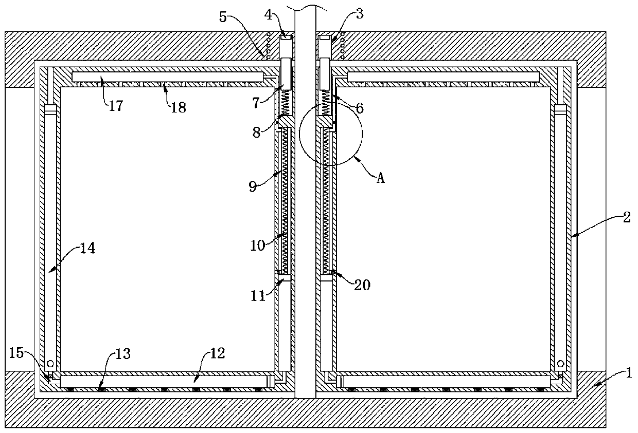
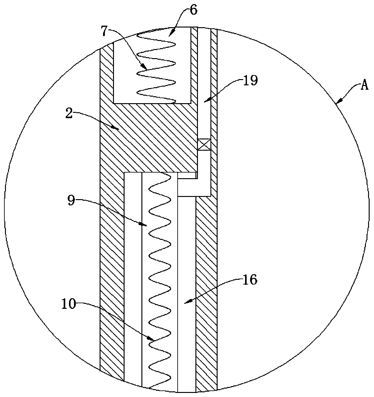
[0026] refer to Figure 2-3 , different from Embodiment 1, an annular airbag 16 is fixedly connected between the upper end of the slider 11 and the inner top of the slider chamber 9, and the upper end of the revolving door frame 2 is provided with an air outlet cavity 17, and the side wall of the annular airbag 16 passes through a one-way air outlet pipe 19 Connected with the air outlet chamber 17, the top of the revolving door frame 2 is provided with an air jet hole 18 communicating with the air outlet chamber 17, and the side wall of the annular air bag 16 is connected with a one-way suction pipe 20, further, the one-way air outlet pipe 19 only allows the gas to flow from the ring The air bag 16 enters the air outlet cavity 17, and the one-way suction pipe 20 only allows gas to enter the annular air bag 16 from the outside. Both the one-way air outlet pipe 19 and the one-way suction pipe 20 can be equipped with a one-way valve inside to realize their functions. .

[0027] ...


PUM


Abstract

The invention discloses a revolving door with an automatic dust removal function. The revolving door comprises a cylindrical door frame; the inner wall of the cylindrical door frame is rotationally connected with a rotating shaft; a plurality of revolving door frames are uniformly distributed and fixedly connected to the side wall of the rotating shaft; a sliding plug cavity is formed in the sidewall, close to the rotating shaft, of the revolving door frame; a sliding plug is elastically connected to the top in the sliding plug cavity through a conductive spring; an annular groove is formed in the lower end of the cylindrical door frame; and a driving device for driving the sliding plug to move on the inner wall of the sliding plug cavity is mounted in the annular groove. When the revolving door frame rotates continuously, a magnetic column reciprocates up and down in the annular groove, so that an induction current is generated to the induction coil, the conductive spring contracts after being electrified to drive the sliding plug to move upwards, space under the sliding plug cavity is increased, the pressure intensity is reduced, dust on a floor mat is sucked into dust suction chambers through one-way dust suction holes, the condition that since dust drifts away with movement of people, people inhales excessive dust, and the health of people is endangered is avoided.

Description

technical field [0001] The invention relates to the technical field of revolving doors, in particular to a revolving door with an automatic dust removal function. Background technique [0002] Because the revolving door integrates the advantages of various door bodies, revolving doors are used as facades in many large shopping malls and office buildings. [0003] When there is a large flow of people in the halls of large shopping malls and office buildings, the coming and going crowd will carry a lot of dust, which will cause a lot of dust to adhere to the floor mat at the lower end of the revolving door, and the dust will float as people walk, making People inhale too much dust, which is harmful to people's health. In addition, for the normal operation of large shopping malls and office buildings, revolving doors generally rotate continuously during the day, making it impossible to effectively clean the dust on the floor mats, making The ground in large shopping malls and ...

Claims


Application Information

Patent Timeline
IPC IPC(8): E06B3/90E06B7/28B08B5/02A47L1/02A47L11/32A47L11/33A47L7/02
CPCA47L1/02A47L7/02A47L11/32A47L11/33B08B5/023E06B3/90E06B7/28
Inventor 姚宏应
Owner 抚州市中小企业服务有限公司
Why Eureka
Try Eureka