
Mobile contact rail detection device and application method thereof

A technology for detection devices and contact rails, which is applied in the direction of measuring devices, optical devices, railway inspection vehicles, etc., can solve the problems of incomplete and accurate reflection of contact rails, limited detection items, and small number, etc., to achieve volume reduction and adaptability Good performance and smooth sampling effect

Pending Publication Date: 2020-07-03
QINGDAO METRO GRP CO LTD +1
View PDF0 Cites 18 Cited by
  • Summary
  • Abstract
  • Description
  • Claims
  • Application Information

AI Technical Summary

Problems solved by technology

[0005] The height difference (guide height) and lateral distance (pull-out value) between the contact rail and the basic rail, as well as the degree of wear (wear) all directly affect the reliability and stability of the traction power source of the subway train. An important parameter, mainly relying on manual and traditional measurement or simple electronic measuring equipment for point-by-point static detection, so the number of samples is relatively small, and the efficiency is low, the detection items are limited, and the status of the contact rail cannot be completely and accurately reflected. In order to ensure continuous and stable current and to ensure that the contact rail is in a normal working state, a more comprehensive inspection of the contact rail plays an important role in improving the quality of the current. This requires us to be able to timely and reliably grasp the work of the contact rail status, make a scientific evaluation and management of it, and make an accurate judgment basis for the subsequent planned maintenance

Method used


Image

  • Mobile contact rail detection device and application method thereof
  • Mobile contact rail detection device and application method thereof
  • Mobile contact rail detection device and application method thereof

Examples


Embodiment Construction

[0077] The present invention will be further described in detail below in conjunction with the accompanying drawings, so that those skilled in the art can implement it with reference to the description.

[0078] It should be understood that terms such as "having", "comprising" and "including" as used herein do not entail the presence or addition of one or more other elements or combinations thereof.

[0079] It should be noted that in the description of the present invention, the orientation or positional relationship indicated by the term is based on the orientation or positional relationship shown in the drawings, which is only for the convenience of describing the present invention and simplifying the description, and does not indicate or imply No device or element must have a specific orientation, be constructed, and operate in a specific orientation and therefore should not be construed as limiting the invention.

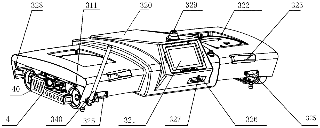
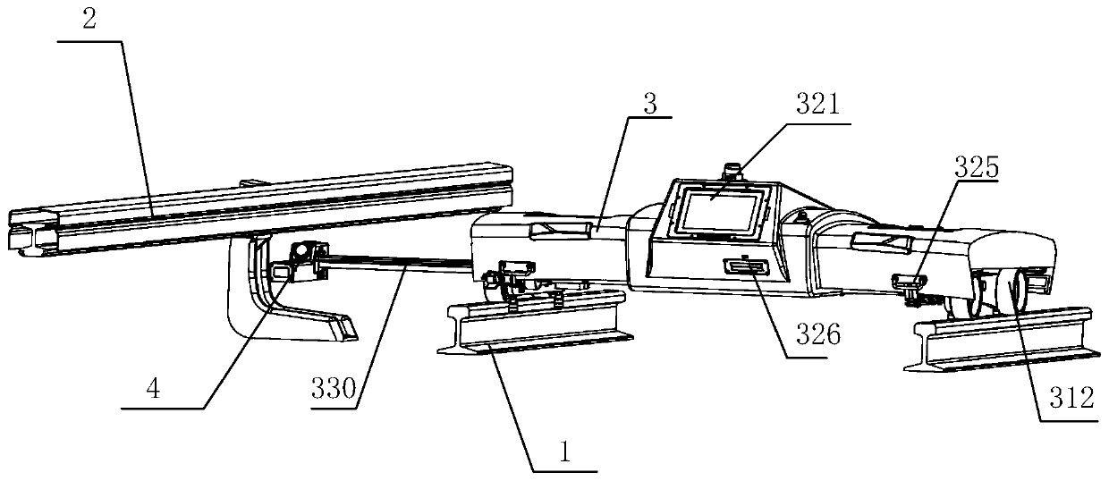
[0080] Figure 1-4 It shows an implementation form of a ...


PUM


Abstract

The invention discloses a mobile contact rail detection device, which comprises a trolley arranged on a rail, wherein one side of the trolley is telescopically provided with a measurement unit capableof extending into the lower part of a contact rail, and the trolley is provided with a host in communication connection with the measurement unit; the measurement unit is configured to comprise a first industrial camera, a second industrial camera and a laser, the first industrial camera and the second industrial camera are matched with the contact rail to acquire 3D point cloud and / or picture information; and the laser is arranged on one side of the second industrial camera. According to the mobile contact rail detection device provided by the invention, a measurement probe can be erected below the contact rail through the arranged telescopic measurement unit on the premise of ensuring a reliable measurement reference so as to carry out continuous scanning measurement on the contact rail. The measurement probe is stored in the main body after being used, so that the measurement probe is protected, and the volume of equipment during transportation is reduced.

Description

technical field [0001] The invention relates to an instrument device for detection. More specifically, the present invention relates to a mobile contact rail detection device used in the detection of subway contact rail and its application method. Background technique [0002] With the rapid increase of urban subway mileage, the task of ensuring the safe, stable and reliable operation of trains is becoming heavier and heavier, and the workload is also increasing. At present, the electricity during the operation of the subway train is mainly obtained through the following two contact methods: [0003] The first is to obtain it from the catenary through the pantograph on the roof. The acquisition method is similar to the current high-speed rail traction power supply system. It is common in many patrol inspection instruments and high-speed rail equipment; [0004] The second way is to supply power through the contact rail. This method is currently a unique power supply method...

Claims


Application Information

Patent Timeline
IPC IPC(8): G01B11/00G01B11/06G01B11/14G01B11/26G01B11/28B61D15/12B61K9/08
CPCB61D15/12B61K9/08G01B11/00G01B11/0608G01B11/14G01B11/26G01B11/28
Inventor 谢鹏程许可谈灝马斌斌米继光顾昕马健谢圣彬张晟刘延普
Owner QINGDAO METRO GRP CO LTD
Learn More